Sheet conveying device, and image forming apparatus including same

a conveying device and conveying technology, applied in the direction of registering devices, thin material processing, article separation, etc., can solve the problems of obstructing the sheet conveying operation, paper jam or a conveyance failure, and the inability to reliably perform the sheet feeding operation, etc., to achieve stable transfer quality, simple configuration, and low cost

Active Publication Date: 2008-08-28
RICOH KK
View PDF15 Cites 22 Cited by
  • Summary
  • Abstract
  • Description
  • Claims
  • Application Information

AI Technical Summary

Benefits of technology

[0051]In light of the foregoing, the inventors of the present application propose to provide, in at least one embodiment, a sheet conveying device and an image forming apparatus including a sheet conveying device that can reduce or even eliminate at least one of the drawbacks of the above-described techniques. In at least one embodiment, a sheet conveying device is provided that is compact and space-saving, that includes a simple configuration achieved at low cost, that can handle various types of sheets, and that can convey various types of sheets in a stable transfer quality and increase flexibility of the design thereof, and an image forming apparatus that includes such sheet conveying device.

Problems solved by technology

However, in the sheet conveying device with the above-described configuration, the following problem arises when conveying a specific type of sheet with high rigidity, such as a cardboard recording paper or an envelope.
As a result, the highly rigid sheet cannot move smoothly along the sheet conveying path, causing a paper jam or a conveyance failure.
Thus, the sheet feeding operation cannot be reliably performed.
Accordingly, when a highly rigid sheet is conveyed, a large force resists this bending action and obstructs the sheet conveying operation.
As a result, the leading edge of the highly rigid sheet may not reach the pair of conveying rollers at the downstream side of the sheet conveying direction, with the result that the sheet may be conveyed only by a pair of rollers on the upstream side thereof.
However, when the sheet is bent by the guide member, the conveying force of the pair of rollers alone may be insufficient for conveying the highly rigid sheet against the resistance caused by the bending action.
As a result, the sheet may be moved obliquely because the center-line of the highly rigid sheet is not aligned with the center-line of the sheet conveying path, or a paper jam occurs because the highly rigid sheet is caught inside the guide member and stops moving.
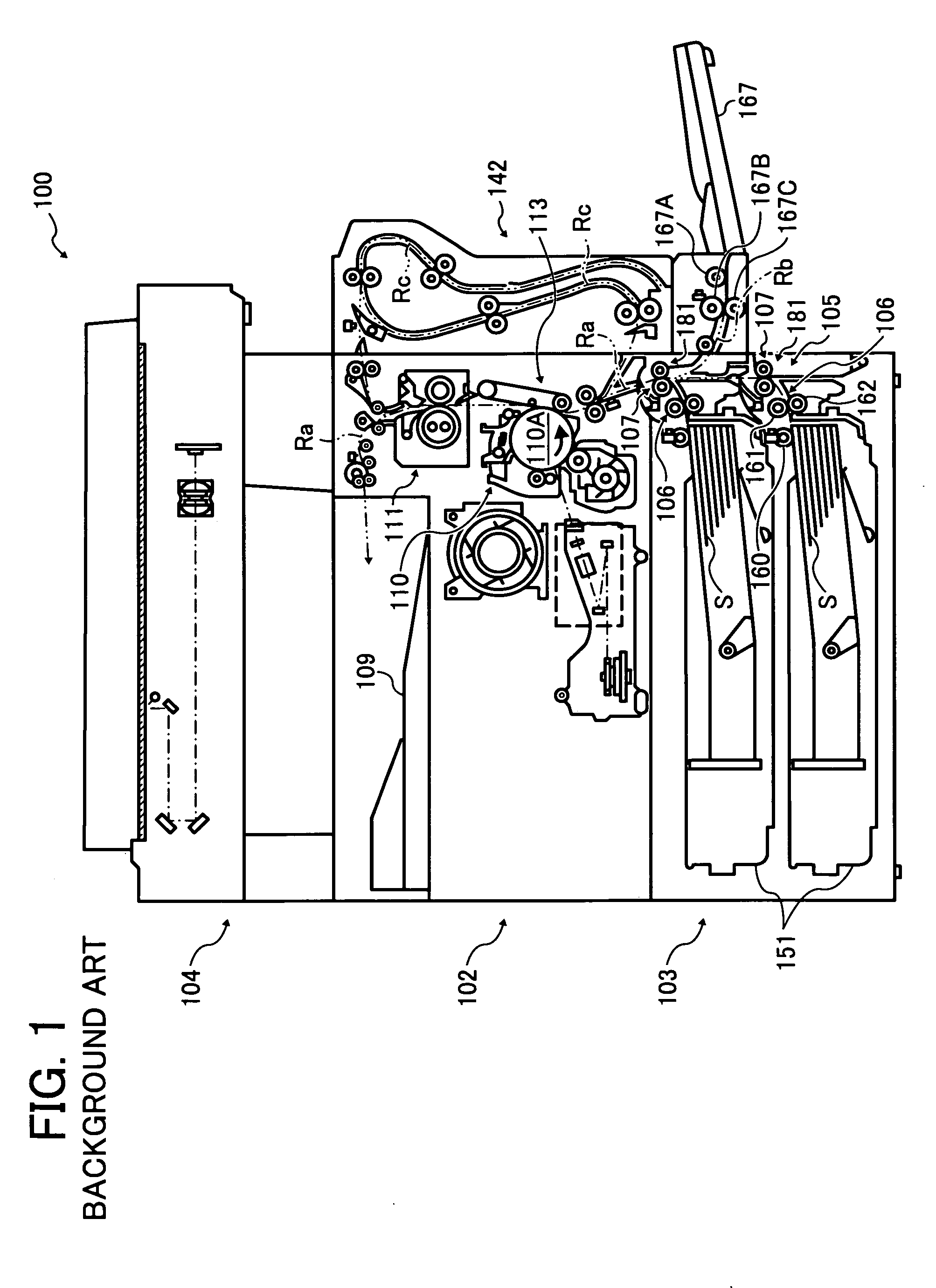
However, the first technique shown in FIG. 1 cannot respond to recent demands for a further width-size reduction of an image forming apparatus and for stable quality in transferring various sheets having different sizes from the first sheet conveying path and the second sheet conveying path.
However, the sheet conveying device using the second technique merely provides a fixed guide member for guiding a conveyed sheet, and thus does not eliminate the speed difference between the moving conveyed sheet and the fixed guide member.
That is, this related-art configuration is insufficient for preventing conveyance failures or paper jams.
Particularly when conveying a highly rigid sheet, such as a cardboard recording paper or an envelope, conveyance failures and paper jams frequently occur and flipping noises made by the trailing edge of the sheet increase considerably.
Accordingly, as with the related-art configuration described above, this related-art technique does not eliminate the relative speed difference between the sheet and the reverse guide member when changing the direction of the sheet and guiding the sheet, thus generating a conveyance load.
Particularly when conveying a highly rigid sheet, such as a cardboard recording paper or an envelope, conveyance failures and paper jams frequently occur and flipping noises caused by the trailing edge of the sheet increase considerably.
However, a conveyance load is still generated nonetheless, and therefore, particularly when conveying a highly rigid sheet, such as a cardboard recording paper or an envelope, conveyance failures and paper jams frequently occur.
However, there are no measures provided for reducing the conveyance load before and after the sheet is supported by the internal rollers, i.e., when the sheet is in contact with the sheet conveying path outside the redirection section.
Particularly when conveying a highly rigid sheet such as a cardboard recording paper or an envelope, conveyance failures and paper jams frequently occur and flipping noises caused by the trailing edge of the sheet increase considerably.

Method used


Image

  • Sheet conveying device, and image forming apparatus including same
  • Sheet conveying device, and image forming apparatus including same
  • Sheet conveying device, and image forming apparatus including same

Examples


Embodiment Construction

[0119]It will be understood that if an element or layer is referred to as being “on”, “against”, “connected to” or “coupled to” another element or layer, then it may be directly on, against, connected or coupled to the other element or layer, or intervening elements or layers may be present. In contrast, if an element is referred to as being “directly on”, “directly connected to” or “directly coupled to” another element or layer, then there are no intervening elements or layers present. Like numbers referred to like elements throughout. As used herein, the term “and / or” includes any and all combinations of one or more of the associated listed items.

[0120]Spatially relative terms, such as “beneath”, “below”, “lower”, “above”, “upper” and the like may be used herein for ease of description to describe one element or feature's relationship to another element(s) or feature(s) as illustrated in the figures. It will be understood that the spatially relative terms are intended to encompass...


PUM

PropertyMeasurementUnit
distanceaaaaaaaaaa
conveying distanceaaaaaaaaaa
conveying path lengthaaaaaaaaaa

Abstract

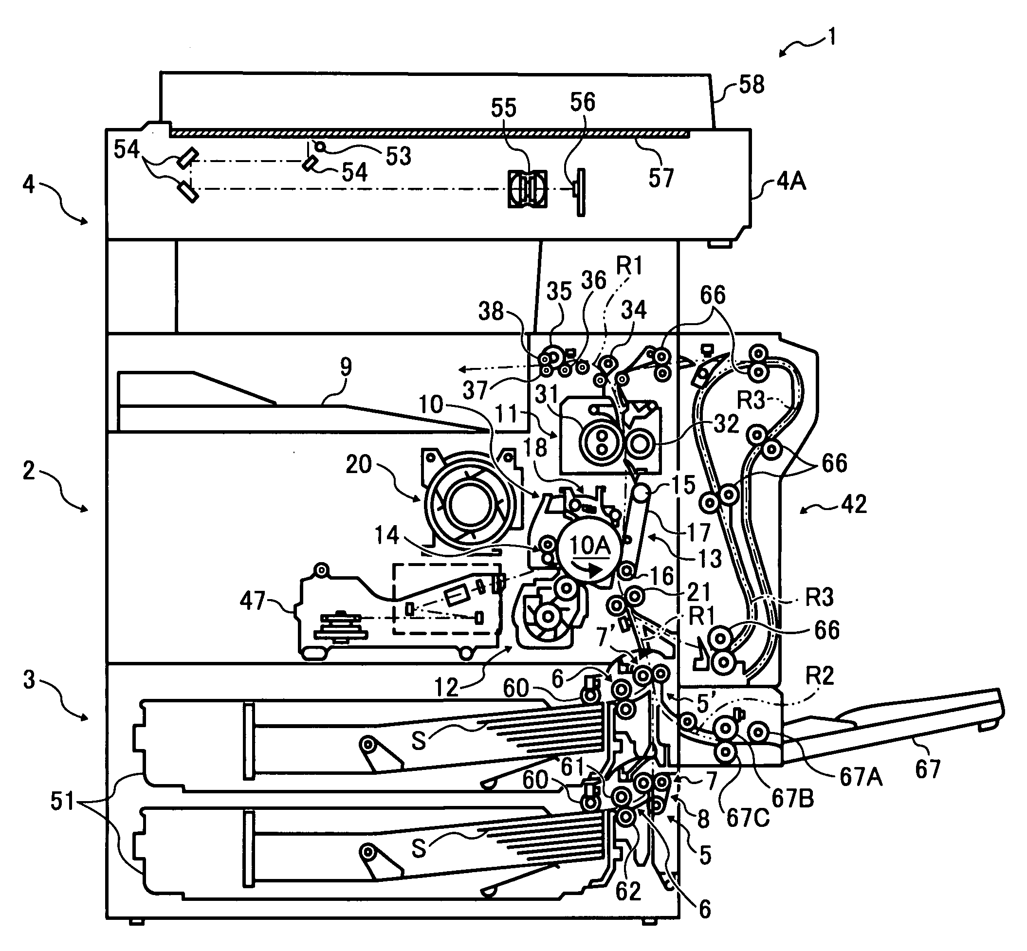
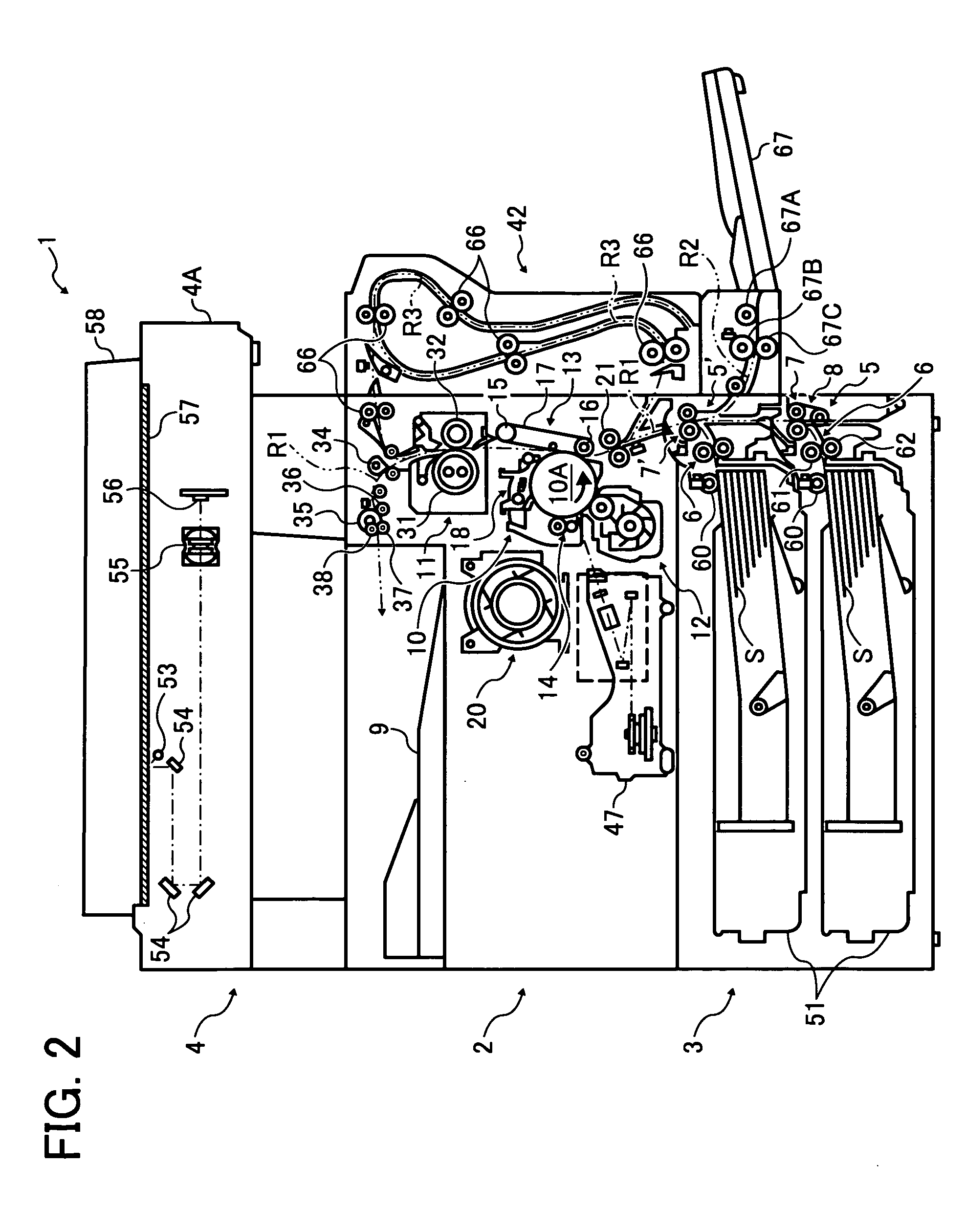
A sheet conveying device, that can be included in an image forming apparatus, includes a first sheet conveying path, a second sheet conveying path, a third conveying path, and a belt-type sheet conveying unit. The first sheet conveying path has a curved portion, and feeds and conveys a sheet therethrough. The second sheet conveying path has a curved portion and different from the first sheet conveying path, and feeds and conveys the sheet therethrough. The third sheet conveying path is provided from a confluence of the first sheet conveying path and the second sheet conveying path. The belt-type sheet conveying unit is disposed on one side of the third sheet conveying path corresponding to an outer side of the curved portion of the first sheet conveying path and an inner side of the curved portion of the second sheet conveying path.

Description

PRIORITY STATEMENT[0001]The present patent application claims priority under 35 U.S.C. §119 from Japanese Patent Application No. 2007-046215 filed on Feb. 26, 2007 in the Japan Patent Office, the contents and disclosure of which are hereby incorporated by reference herein in their entirety.BACKGROUND[0002]1. Field[0003]Example embodiments of the present patent application generally relate to a sheet conveying device effectively conveying various types of sheets, an image forming apparatus such as a copier, a facsimile machine, a printer, a printing machine, an inkjet recording device, a scanner provided with the sheet conveying device, and / or a multifunctional machine combining functions of at least two of the above.[0004]2. Discussion of the Related Art[0005]In order to reduce the overall sizes and dimensions of related-art image forming apparatuses including copiers such as a plain paper copier or PPC and an electrophotographic copier, facsimile machines, printers, printing machin...

Claims


Application Information

Patent Timeline
Patent Type & Authority Applications(United States)
IPC IPC(8): B65H3/44B65H5/02
CPCB65H3/44B65H5/025B65H5/062B65H5/26B65H5/36B65H2407/21B65H2301/4454B65H2404/262B65H2404/6111B65H2404/612B65H2301/33312
Inventor WATASE, HIROYUKIUEDA, MASAYUKI
Owner RICOH KK
Why Eureka
Try Eureka