Magnetic sensor, magnetic direction sensor, method of detecting magnetic field and method of detecting magnetic direction

Active Publication Date: 2008-08-28
TDK CORPARATION
View PDF4 Cites 32 Cited by
  • Summary
  • Abstract
  • Description
  • Claims
  • Application Information

AI Technical Summary

Benefits of technology

[0006]All of the four GMR elements configuring the bridge circuit as described in Japanese Unexamined Patent Application Publication No. 2003-66127 are required to exhibit the same resistance in the condition where no detected magnetic field is applied (i.e. the measurement wait condition). Even if one of the four GMR elements exhibits a different resistance, a differential output (an offset voltage) of the bridge circuit may be generated even in the measurement wait condition. The resistance in each GMR element can be determined mainly by the angle formed between the magnetization

Problems solved by technology

In fact, there are relatively large variations (manufacturing errors) in the angle formed between the anisotropic magnetic field direction and the magnetization direction of the pinned layer.
Therefore, it is extremely difficult to completely eliminate th

Method used


Image

  • Magnetic sensor, magnetic direction sensor, method of detecting magnetic field and method of detecting magnetic direction
  • Magnetic sensor, magnetic direction sensor, method of detecting magnetic field and method of detecting magnetic direction
  • Magnetic sensor, magnetic direction sensor, method of detecting magnetic field and method of detecting magnetic direction

Examples


Embodiment Construction

[0067]Preferred embodiments of the present invention will now be described in detail with reference to the accompanying drawings.

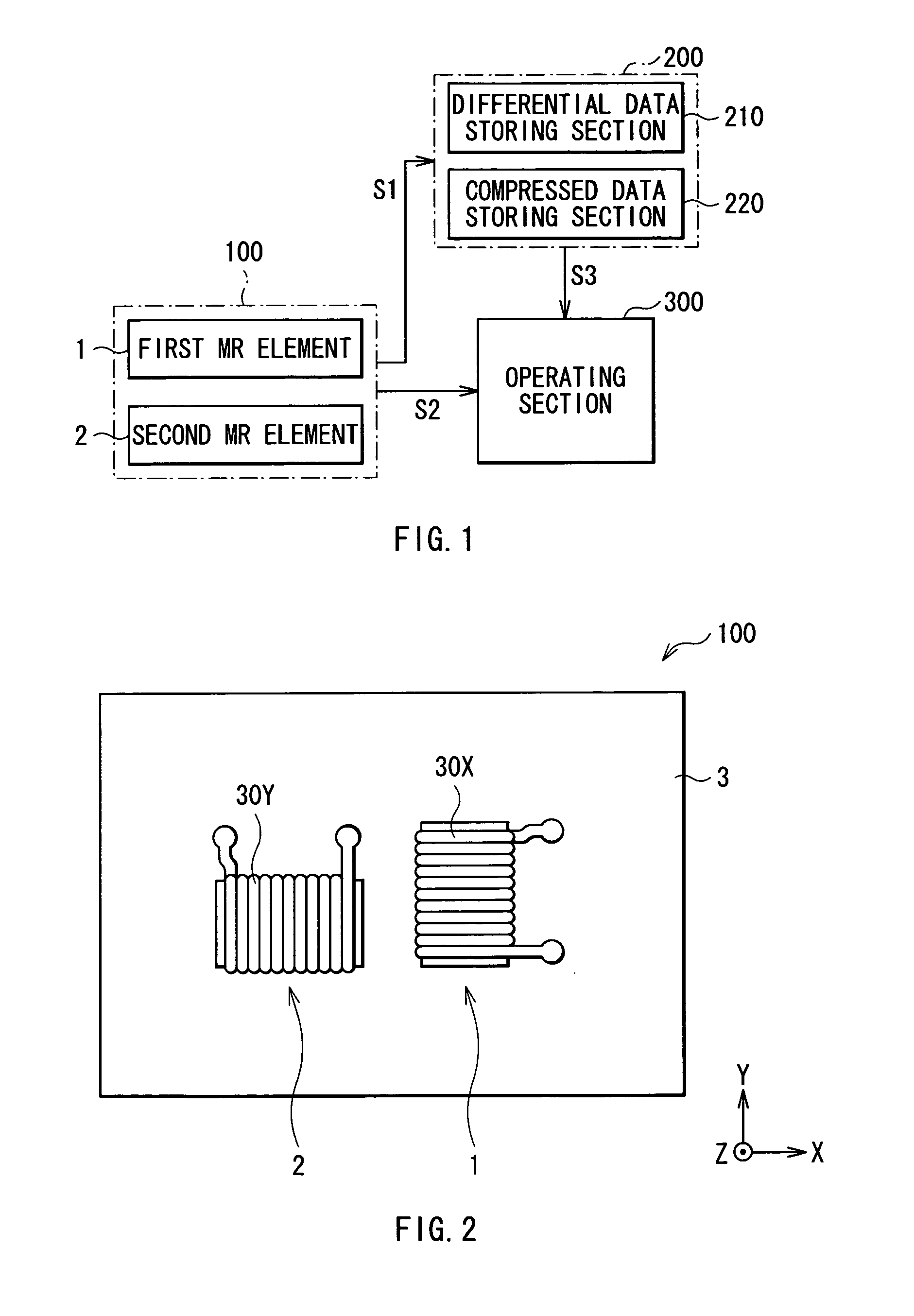
[0068]The configuration of a magnetic direction sensor as a preferred embodiment in the present invention will be firstly described with reference to FIG. 1 and the like. FIG. 1 is a block diagram showing the entire configuration of the magnetic direction sensor of the present embodiment. A magnetic sensor of the present invention includes the magnetic direction sensor described below.

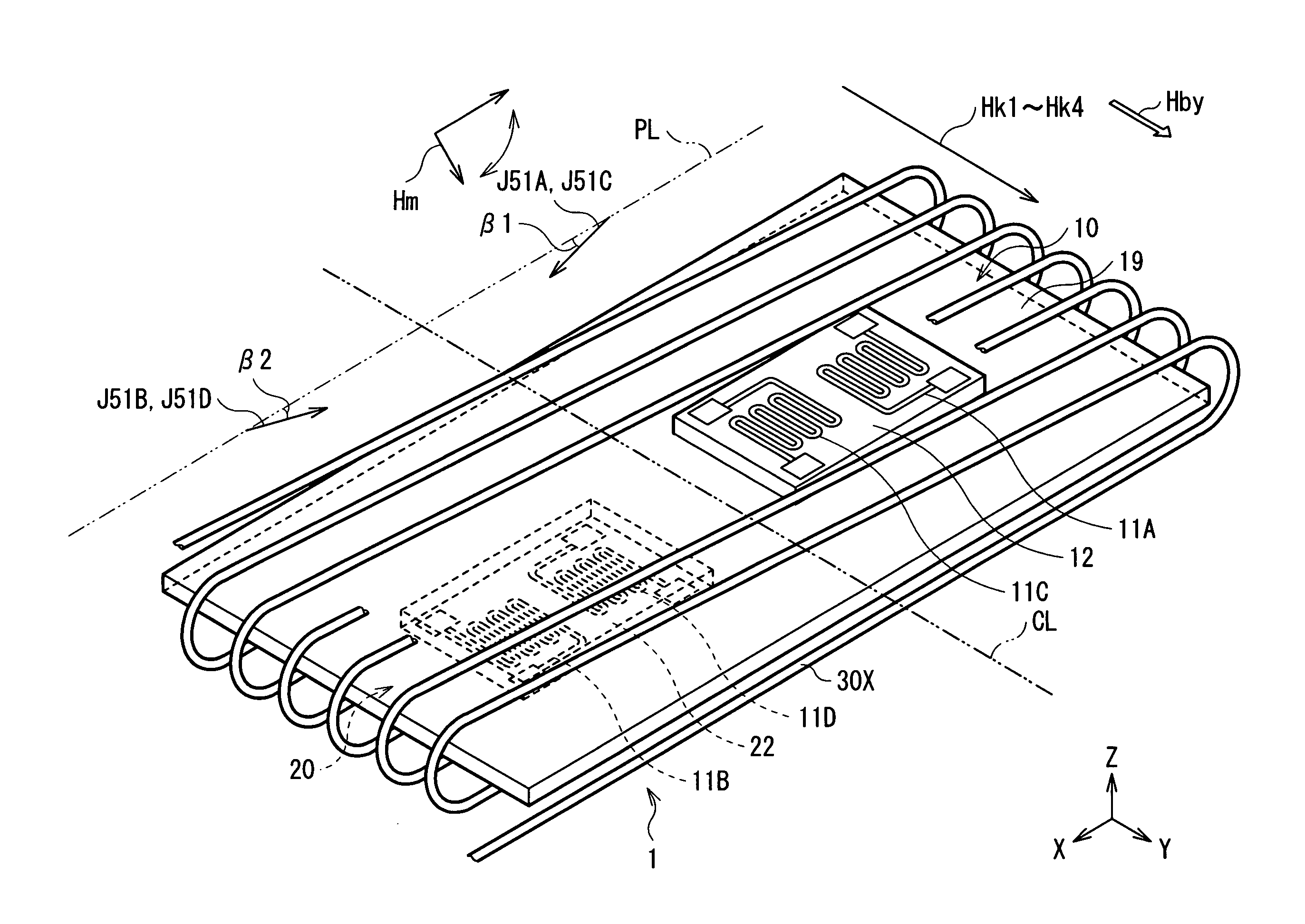
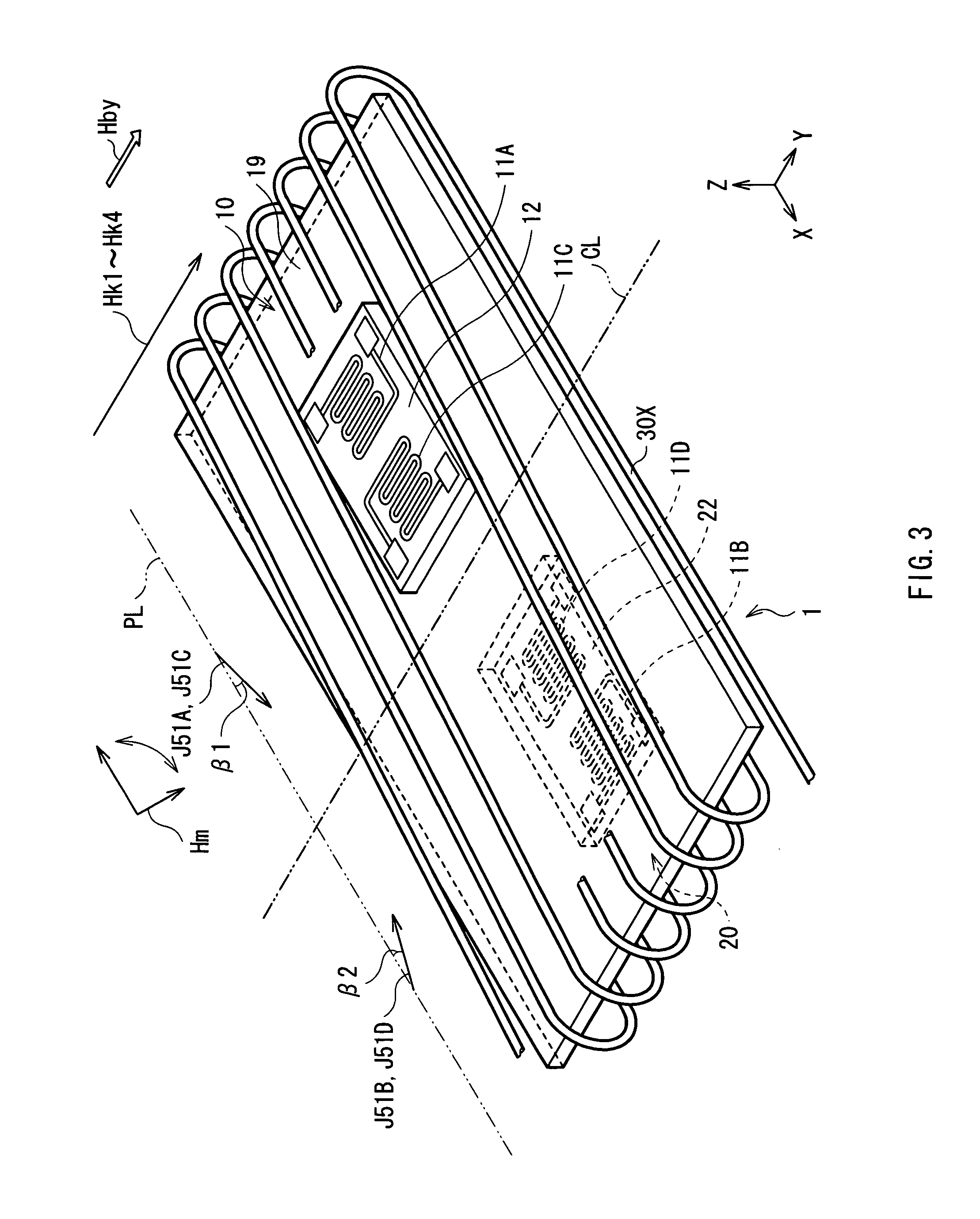
[0069]The magnetic sensor is provided with a measuring section 100, a storage section 200 and an operating section 300. The measuring section 100 has a first magnetoresistive (MR) element 1 and a second magnetoresistive (MR) element 2, and coils 30 (30X and 30Y), which apply bias magnetic fields Hb (Hbx and Hby) to these elements, respectively. The measuring section 100 detects the resistance values of the first and second MR elements 1 and 2 in accordance with an attitude ch...


PUM


Abstract

A magnetic direction sensor can detect at higher precision the magnitude and direction of a detected magnetic field. The magnetic direction sensor has a measuring section, a storage section and an operating section. The measuring section has first and second MR elements, and detects resistance values of these elements in accordance with an attitude change of the sensor and the presence or absence of a bias magnetic field to be applied through a coil in a direction orthogonal to a magnetization direction of each pinned layer in the first and second MR elements. The storage section stores fixed data invariable in response to a detected magnetic field direction, in resistance values of these elements measured by the measuring section. The operating section calculates a detected magnetic field vector from variable data of resistance values of these elements measured by the measuring section, and fixed data stored in the storage section.

Description

BACKGROUND OF THE INVENTION[0001]1. Field of the Invention[0002]The present invention relates to a magnetic sensor capable of detecting a change in a magnetic field with high sensitivity, and a method of manufacturing the magnetic sensor.[0003]2. Description of the Related Art[0004]As a magnetic sensor for detecting the direction of a micro magnetic field such as geomagnetism, there has been known one using an anisotropic magnetoresistive element formed of a ferromagnetic material such as permalloy (for example, refer to Japanese Patent No. 3318762 and Japanese Unexamined Patent Application Publication No. Hei 6-174471).[0005]Recently, there has been developed a magnetic sensor provided with a plurality of giant magnetoresistive elements (GMR) exhibiting higher detective sensitivity to a change in a magnetic field than the anisotropic magnetoresistive effect element (for example, refer to Japanese Unexamined Patent Application Publication No. 2003-66127). In this type of the magneti...

Claims


Application Information

Patent Timeline
IPC IPC(8): G01R33/09
CPCG01R33/093B82Y25/00
Inventor SHOJI, SHIGERU
Owner TDK CORPARATION
Why Eureka
Try Eureka