Communications system and protocol for medical environment

a communication system and medical environment technology, applied in the field of communication, can solve problems such as failure of communication link establishment, and achieve the effect of safe and reliable connection

Active Publication Date: 2008-08-28
RAULAND BORG
View PDF12 Cites 52 Cited by
  • Summary
  • Abstract
  • Description
  • Claims
  • Application Information

AI Technical Summary

Benefits of technology

[0006]A wireless communications link and associated protocol interconnect a pair of bed and wall units that communicate patient information, including bed exit alerts, from a patient supporting equipment to a hospital nurse call system. In one embodiment, the bed / wall unit pair operates within unlicensed spectrum and, therefore, takes into account possibility of congestion and interference in order to provide safe and reliable connection to the nurse call system. Specifically, a linking procedure aids the establishment of a communications link between the bed and wall units and prevents unintended cross linking of the paired units to other nearby bed and wall units. During the linking procedure, the establishment of the communications link fails upon detection of a third communications device such as a bed or wall unit attempting to participate in the linking process.

Problems solved by technology

During the linking procedure, the establishment of the communications link fails upon detection of a third communications device such as a bed or wall unit attempting to participate in the linking process.

Method used


Image

  • Communications system and protocol for medical environment
  • Communications system and protocol for medical environment
  • Communications system and protocol for medical environment

Examples


Embodiment Construction

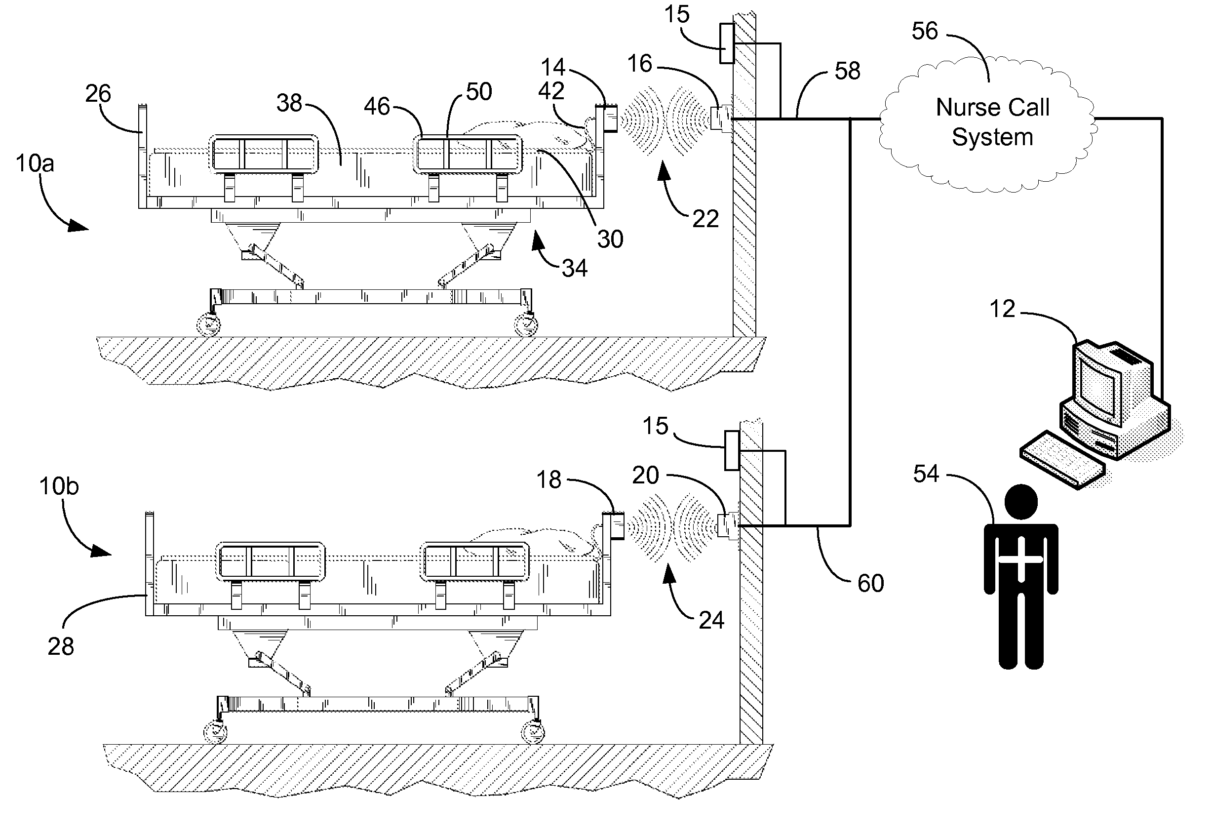
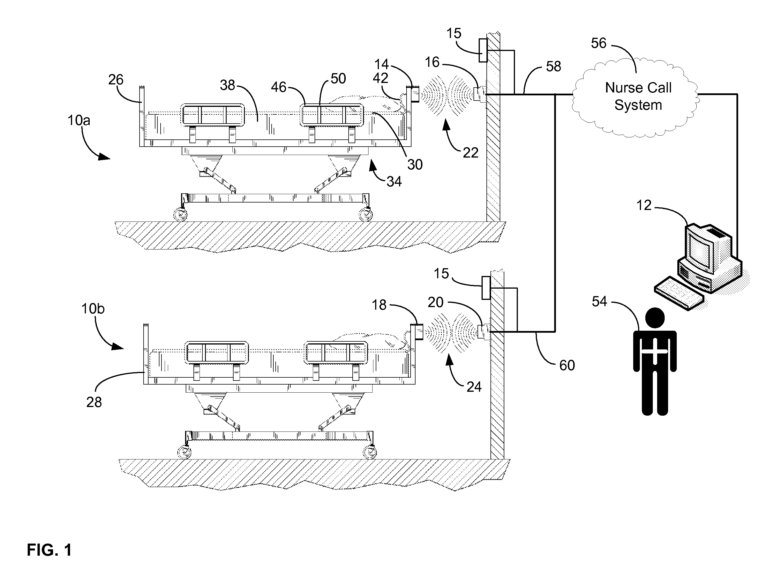
[0028]Turning to the drawings and referring first to FIG. 1, a typical hospital facility environment has multiple hospital beds connected to a hospital monitoring and alerting system. In FIG. 1, only two hospital rooms 10a and 10b are illustrated. Each of the rooms 10a and 10b are identically equipped.

[0029]For ease of explanation, whenever detailed reference is made hereinafter to the equipment in one of the rooms 10a and 10b, the description applies equally well to the other room in FIG. 1, unless indicated otherwise. Moreover, FIG. 1 is representative of a larger environment such as a hospital that may include many more rooms such as the two illustrated in FIG. 1 that are also equipped in the same or similar manner. All of the rooms may be connected to a common nurse call system as suggested by FIG. 1 or there may be several nurse call systems with each of them connecting a group of rooms. All such networking architectures and others are contemplated by the detailed description s...


PUM


Abstract

A communications system and protocol are described for wirelessly interconnecting a pair of bed and wall units that communicate the patient information, including bed exit alerts, from the patient supporting equipment to the hospital nurse call system. A linking procedure is provided for establishing a communications link to interconnect the pair of units, wherein the communications link fails upon detection of a third communications device simultaneously undergoing the link attempt mode. In one embodiment, the system provides for advanced collision detection by monitoring corruption of the end-of-packet byte within the periodic check-in message sequences between the linked units to prevent data corruption and future collisions. To ensure prompt interconnection of units, embodiments of the invention provide for a link reminder to alert the health care provider to initiate the steps for linking the bed and wall units whenever two or more unlinked units are in proximity.

Description

CROSS REFERENCE TO RELATED APPLICATIONS[0001]This application is related to U.S. application Ser. No. <Aty. Dkt. No. 256159> to Perkins, Gallagher, and Garcia and U.S. application Ser. No. <Aty. Dkt. No. 256161> to Perkins, Parrish, and Garcia, both entitled “Communications System And Protocol For Medical Environment” and both filed on Feb. 22, 2007. Each of above applications is incorporated by reference in its entirety herein.FIELD OF THE INVENTION[0002]This invention relates generally to the field of communications and more specifically to the field of medical communications devices.BACKGROUND OF THE INVENTION[0003]Modern health care environments place heavy burdens on medical personnel responsible for a continuously growing number of patients. Nursing shortages and heavy workloads continue to be the norm in most modern hospitals. Nursing and other front line medical caregivers are typically responsible for monitoring and reporting patient conditions. A patient's post...

Claims


Application Information

Patent Timeline
Patent Type & Authority Applications(United States)
IPC IPC(8): H04B7/00
CPCA61B5/0002A61G2203/70A61B5/6887A61B5/6892A61G12/00G06F19/327H04W24/00H04W28/04H04W74/08H04W76/027H04W88/04A61B5/6891A61B2560/0204A61B2560/0219A61B2562/226A61B2562/227A61B5/1113G16H40/20H04W76/18
Inventor PERKINS, MICHAEL C.GARCIA, REUBEN P.GALLAGHER, LAWRENCE W.
Owner RAULAND BORG
Why Eureka
Try Eureka