Sensitive silicon microphone with wide dynamic range
Inactive Publication Date: 2008-08-28
YAMAHA CORP
View PDF5 Cites 67 Cited by
Summary
Abstract
Description
Claims
Application Information
AI Technical Summary
This helps you quickly interpret patents by identifying the three key elements:
Problems solved by technology
Method used
Benefits of technology
Benefits of technology
[0011]It is therefore an important object of the present invention to provide a semiconductor microphone, which has a wide dynamic range and a high sensitivity in a relatively low sound pressure range.
[0013]It is yet another important object of the present invention to provide a compact directional semiconductor microphone.
Problems solved by technology
However, it is hard to convert faint sound to the electric signal.
However, it is difficult to for designers of a general purposesilicon microphone exactly to forecast all the operation environments.
Although plural acoustic transducers are found to form a prior art microphone device for giving directionality to the prior art microphone device, the plural acoustic transducers make the prior art directional microphone device bulky.
In other words, it is difficult to fabricate a compact directional microphone device from the plural acoustic transducers.
Method used
Image
Click on the blue label to locate the original text in one second.
Reading with bidirectional positioning of images and text.
Examples
first embodiment
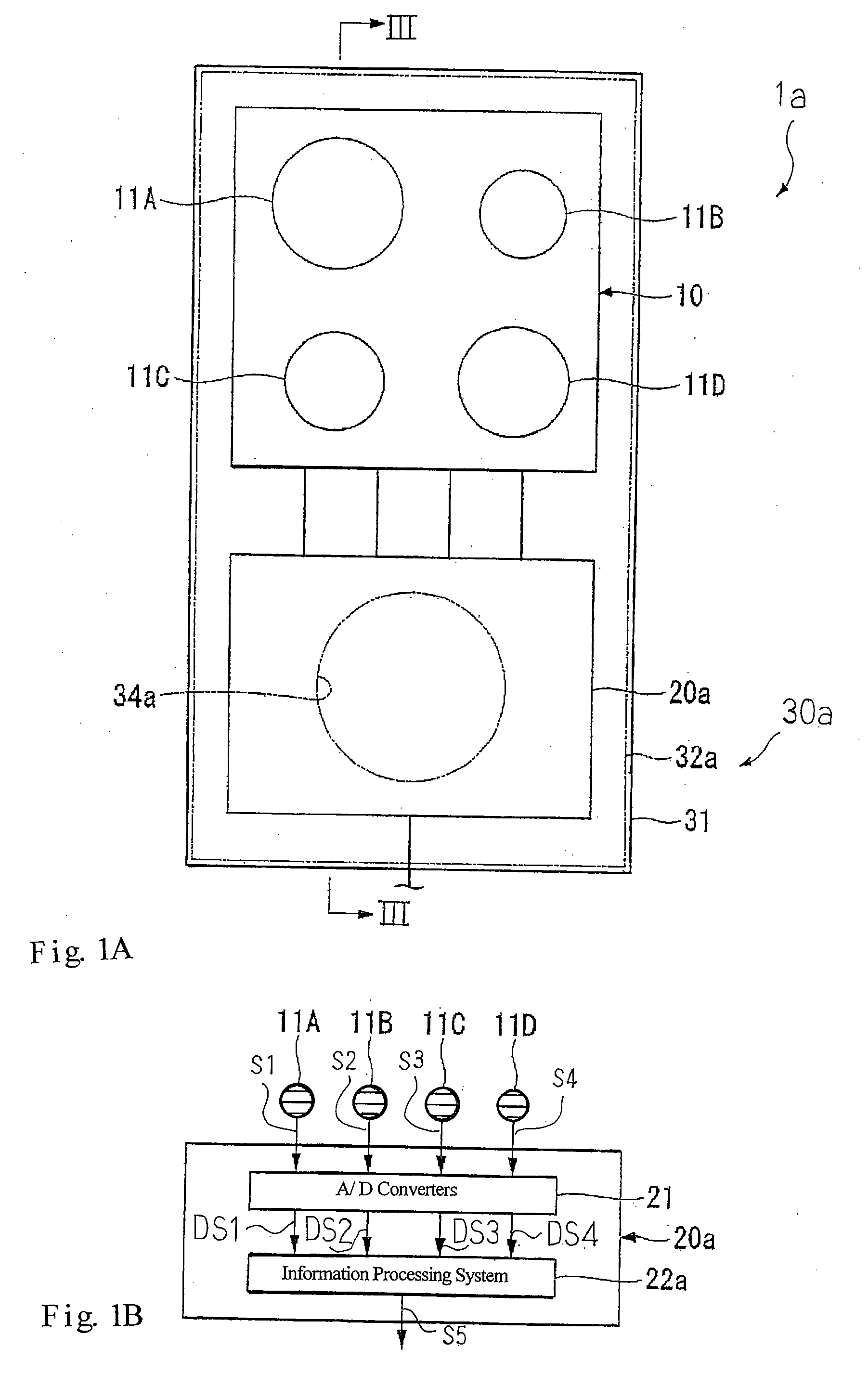
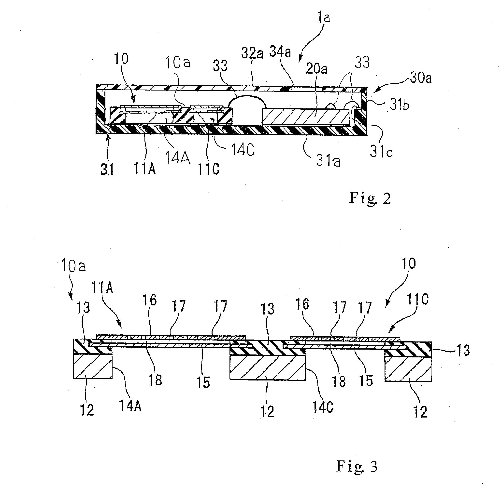
[0048]Referring first to FIGS. 1A and 1B of the drawings, a silicon microphone 1a embodying the present invention largely comprises a silicon microphone device 10, an integrated circuit device 20a and a single package 30a. The silicon microphone 1a is, by way of example, provided in a mobile telephone and a PDA (Personal Digital Assistant).
[0049]An inner space is defined inside the package 30a, and the silicon microphone device 10 and integrated circuit device 20a are accommodated in the package 30a. The package 30a is formed with a sound hole 34a. Since a lid 32a is removed from the package 30a shown in FIG. 1A, dots-and-dash line is indicative of the location of the sound hole 34a. The sound waves enter the inner space through the sound hole 34a, and reach the silicon microphone device 10.
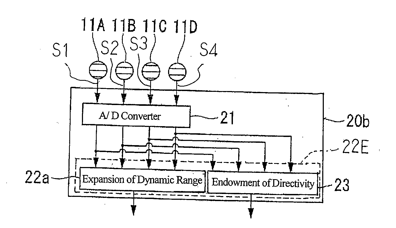
[0050]The silicon microphone device 10 is electrically connected to the integrated circuit device 20a. The sound waves are converted to four intermediate acoustic signals S1, S2, S3 and S4 throug...
second embodiment
[0111]Turning to FIG. 11 of the drawings, another silicon microphone 1b embodying the present invention largely comprises plural acoustic transducers 11A, 11B, 11C and 11D and an integrated circuit device 22b. The acoustic transducers 11A to 11D are same as those of the first embodiment, and no further description is hereinafter incorporated for the sake of simplicity.
[0112]The integrated circuit device 22b is adapted to achieve a function, i.e., “composition 227b”, through which the intermediate acoustic signals S1 to S4 compose a composite acoustic signal DS5a. For the composition 227b, the integrated circuit device 22b calculates a sum of values expressing the amplitude of the intermediate acoustic signals S1 to S4 or a square root of the sum of square values. In this instance, analog-to-digital converters and a microcomputer are integrated on a single semiconductor chip, and the following function is realized through an execution of a computer program.
[0113]FIG. 12 shows the fun...
third embodiment
[0118]Turning to FIG. 13 of the drawings, yet another silicon microphone 1c embodying the present invention largely comprises plural acoustic transducers 11A to 11D and an integrated circuit device 22c. The acoustic transducers 11A to 11D are similar to those of the first embodiment, and, for this reason, are not hereinafter detailed. Boxes 221b, 222, 223b, 224, 225, 226aA to 226aC, 227c, 229A to 229C and 230 and circles 228A to 228C stand for functions of the integrated circuit device 22c.
[0119]The normalization 226aA, 226aB and 226aC are similar to those of the first embodiment, and the composition 227a and composition control 221a are replaced with a composition 227c and composition control 221b, respectively. For this reason, description is focused on the composition 227c and composition control 221b.
[0120]The composition control 221b is broken down into sub-functions of “acquisition of sound pressure data 222”, “selection of acoustic transducer 223b”, “acquisition of saturate...
PUM
Abstract
A siliconmicrophone includes a siliconmicrophone device, on which four acoustic transducers are integrated, an integrated circuit device and a package for housing the devices in an inner space defined therein, and the four acoustic transducers have different values of sensitivity and, accordingly, different values of dynamic range; the analog acoustic signals are supplied from the four acoustic transducers to the integrated circuit device, and are converted to digital acoustic signals; the digital acoustic signal output from the acoustic transducers with relatively high sensitivity are normalized with respect to the digital acoustic signal output from the acoustic transducer with lowest sensitivity, and the normalized digital acoustic signals are selectively formed into a composite acoustic signal depending upon the sound pressure of sound waves so that the dynamic range is expanded without sacrifice of high sensitivity in the low sound pressure range.
Description
FIELD OF THE INVENTION[0001]This invention relates to a microphone and, more particularly, to an electrostatic microphone fabricated on a semiconductor substrate.DESCRIPTION OF THE RELATED ART[0002]Growing research and development efforts are being made for miniature microphones. Various approaches have been proposed. One of the approaches is disclosed in Japan Patent Application laid-open No. 2001-169395. The prior art miniature microphone disclosed in the Japan Patent Application laid-open is of the type optically converting vibrations of extremely thin vibratory plates to an electric signal, and, accordingly, is called as “an optical microphone”.[0003]The prior art optical microphone is hereinafter described. An inner space is defined inside a package, and is divided into plural chambers by means of photo-shield walls. The chambers are respectively assigned to acoustic transducers, i.e., acoustic waves-to-electric signalconverters, and each of the acoustic transducers is constit...
Claims
Application Information
Patent Timeline
Application Date:The date an application was filed.
Publication Date:The date a patent or application was officially published.
First Publication Date:The earliest publication date of a patent with the same application number.
Issue Date:Publication date of the patent grant document.
PCT Entry Date:The Entry date of PCT National Phase.
Estimated Expiry Date:The statutory expiry date of a patent right according to the Patent Law, and it is the longest term of protection that the patent right can achieve without the termination of the patent right due to other reasons(Term extension factor has been taken into account ).
Invalid Date:Actual expiry date is based on effective date or publication date of legal transaction data of invalid patent.

