Chip actuator cover assembly

Active Publication Date: 2008-08-28
ESSAI INC
View PDF12 Cites 10 Cited by
  • Summary
  • Abstract
  • Description
  • Claims
  • Application Information

AI Technical Summary

Benefits of technology

[0009]In one preferred aspect of the invention, the front, back, and sides of the carrier housing define a central cavity region above the pedestal assembly for permitting air flow through the carrier housing to improve the heat dissipation capability of the cover assembly. This

Problems solved by technology

The difficulty with such prior socket cover designs is that the threaded depressor construction is relatively rigid and bulky, and involves frictional forces that impair the ability of the d

Method used


Image

  • Chip actuator cover assembly
  • Chip actuator cover assembly
  • Chip actuator cover assembly

Examples


Example

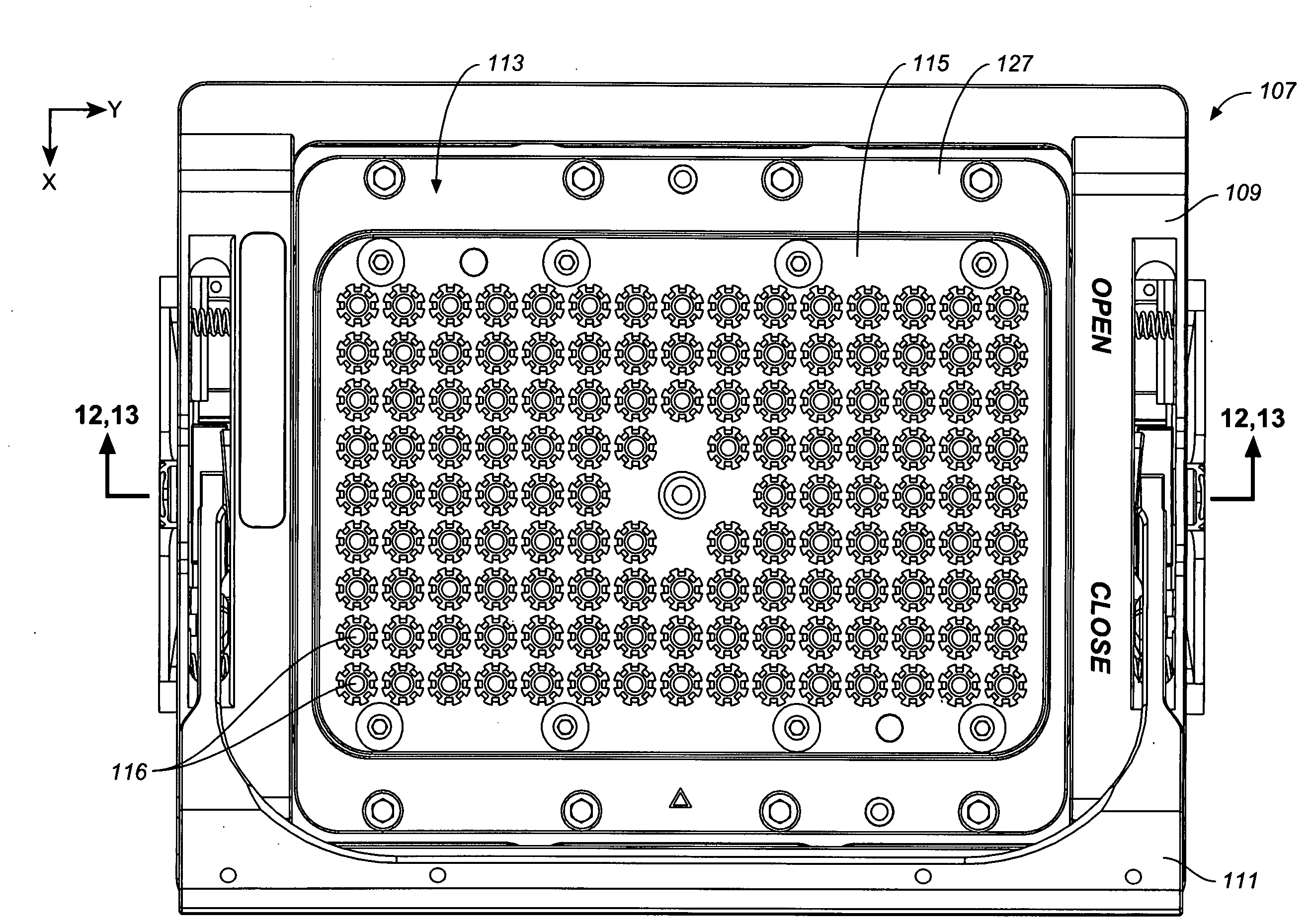
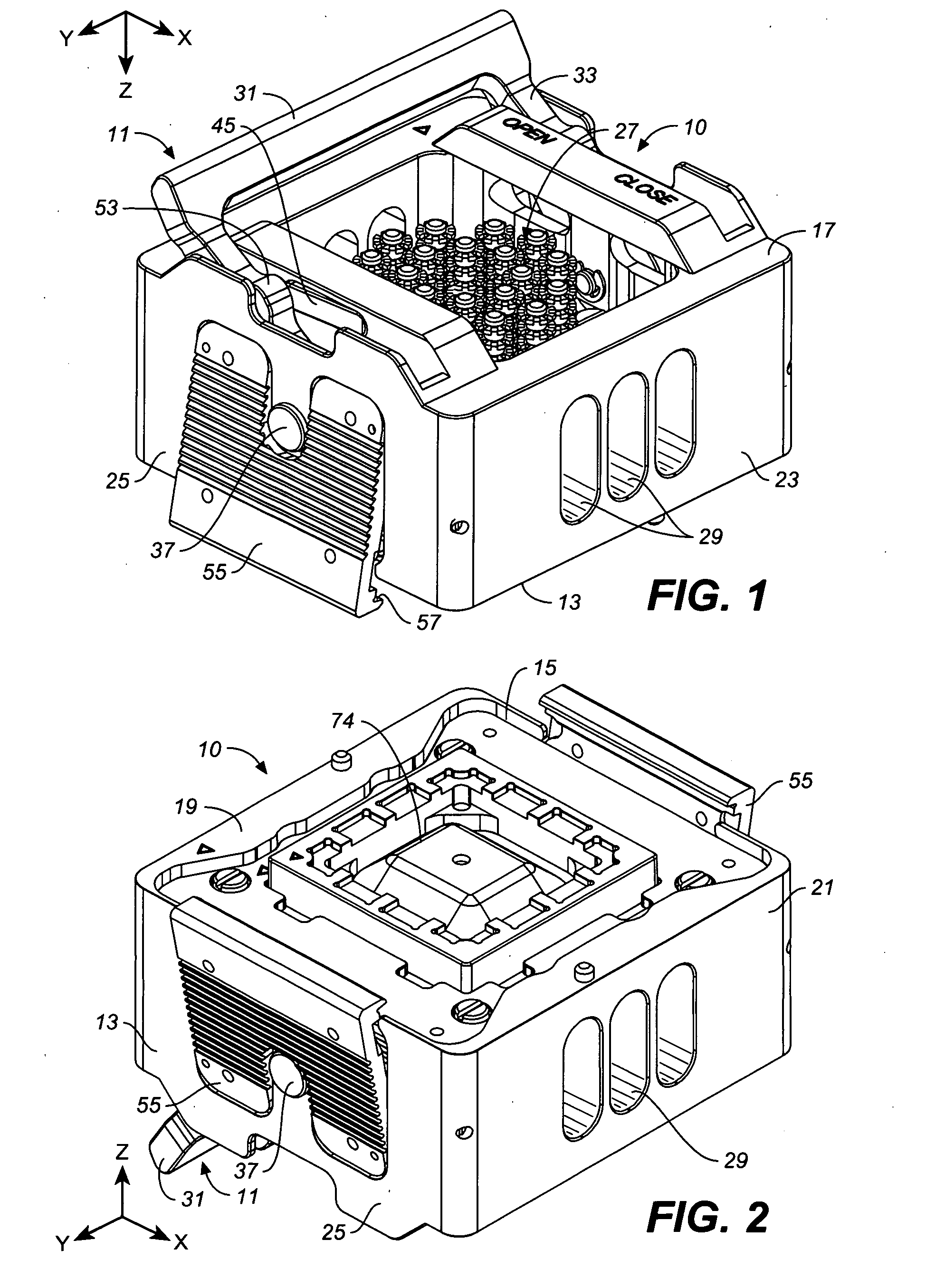
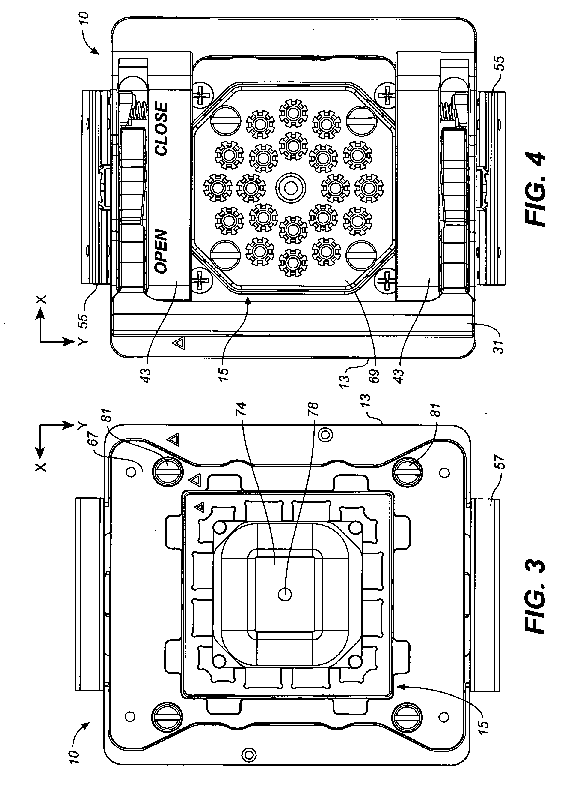
[0031]The accompanying drawings illustrate two possible versions of an IC chip actuator cover assembly in accordance with the present invention. FIGS. 1-9A illustrate a version adapted for use with a relatively low profile bare die chip package such as graphically illustrated in FIG. 10, whereas FIGS. 12-16 illustrate an embodiment of the chip actuator cover assembly adapted for use with IHS (integrated heat spreader) chip packages, such as illustrated in FIG. 11, having a relatively large heat spreader body surrounding a silicon chip. It is understood that other configurations of the chip actuator cover assembly of the invention can be devised for particular applications.

[0032]Turning to the embodiment illustrated in FIGS. 1-9A, the chip actuator cover assembly generally denoted by the numeral 10 has an actuator mechanism 11, a carrier housing 13 for the actuator mechanism, and a pedestal assembly 15. The carrier housing is generally defined by a top 17, a bottom 19, a front 21, a ...


PUM


Abstract

An improved IC chip actuator cover assembly for an IC socket includes a pedestal assembly spring-mounted to the bottom of a carrier housing and side leaf springs or other similar force transferring means on the pedestal assembly which transmit a z-axis force to the corner regions of the pedestal assembly for advancing the pedestal assembly in the z-axis direction against an IC chip in the IC socket. The compliance of the leaf springs maintains a constant and precise actuating force on the IC chip when the IC chip is contacted by the pusher end portion or portions of the pedestal assembly. In a preferred aspect of the invention, the front, back, and sides of the carrier housing define a central cavity region above the pedestal assembly for permitting air flow through the carrier housing to improve the heat dissipation capability of the cover assembly.

Description

CROSS-REFERENCE TO RELATED APPLICATIONS[0001]This application claims the benefit of U.S. provisional application Ser. No. 60 / 903,161 filed Feb. 23, 2007, now pending, the entirely of which is incorporated herein by reference.BACKGROUND OF THE INVENTION[0002]The present invention generally relates to sockets for integrated circuit (IC) devices, and, more particularly, to the construction of covers for IC sockets which hold IC chips in electrical contact with the pin array of the socket.[0003]Sockets for holding IC chip packages are widely known and used in a variety of industrial applications for achieving efficient electrical contact between the I / O contact array of an IC device and the conductor pads of a circuit board. Such applications include test sockets for mounting a device under test (DUT) to a test board and contactor sockets for removably mounting an IC device to a printed circuit board. The socket functions to precisely position the IC device over the pin array of a test ...

Claims


Application Information

Patent Timeline
IPC IPC(8): H01R13/62
CPCG01R1/0466
Inventor BARABI, NASSERKRYACHEK, OKSANAHO, CHEE-WAH
Owner ESSAI INC
Why Eureka
Try Eureka