
Helmet suspension system

Inactive Publication Date: 2008-09-04
JDC RES & DEV CORP
View PDF12 Cites 50 Cited by
  • Summary
  • Abstract
  • Description
  • Claims
  • Application Information

AI Technical Summary

Benefits of technology

[0006]A suspension system may be attached to a helmet which generally allows unrestricted movement of the head of the wearer. The head may move at a normal speed when engaged in a physical activity but the system may provide a counterforce to prevent rapid head movement occasioned in a crash or other similar violent misfortune. The suspension system may comprise a plurality of pistons that are interconnected to each other via a tube with a small inner diameter. During normal head movement, the fluid is exchanged between the pistons and / or a reservoir at a low rate via the tube so that the head can easily move or move with negligible resistance. However, upon encountering a rapid movement, the viscosity of the fluid and the small inner diameter tube prevents rapid exchange of fluid through the tube and thereby also prevents rapid movement of the head. The reason is that there may be a steep rise is viscous friction when the fluid is forced through a single fixed orifice (i.e., the tube).
[0007]A head protection system is provided herein comprising a helmet having a rigid exterior shell. The system may also comprise a shoulder cuff, a plurality of pistons, a viscous fluid, and a tube. The shoulder cuff may be disposable over left and right shoulders of a wearer. The pistons may each define a first end portion pivotably attached to the rigid exterior shell of the helmet and a second end portion pivotably attached to the shoulder cuff. Each of the pistons may also define a fluid cavity. The viscous fluid may be disposed within the fluid cavities of the pistons. The tube may fluidicly connect the fluid cavities allowing transfer of fluid from the fluid cavity of one piston to the fluid cavity of another piston. The tube may have a sufficiently small inner diameter to allow relatively free movement of the wearer's head under normal circumstances but restricts sudden movement of the wearer's head due to the viscosity of the fluid and the small inner diameter.

Problems solved by technology

Activities that involve high speed, such as motocross racing, boating, flying all involve a risk of a high speed crash.
Unfortunately, upon impact, the seatbelts may prevent the body of the participant from lunging forward.
However, the head of the participant may not be restrained.
Such movement of the head with respect to the body may cause injuries to the person's neck and back.

Method used


Image

  • Helmet suspension system
  • Helmet suspension system
  • Helmet suspension system

Examples


Embodiment Construction

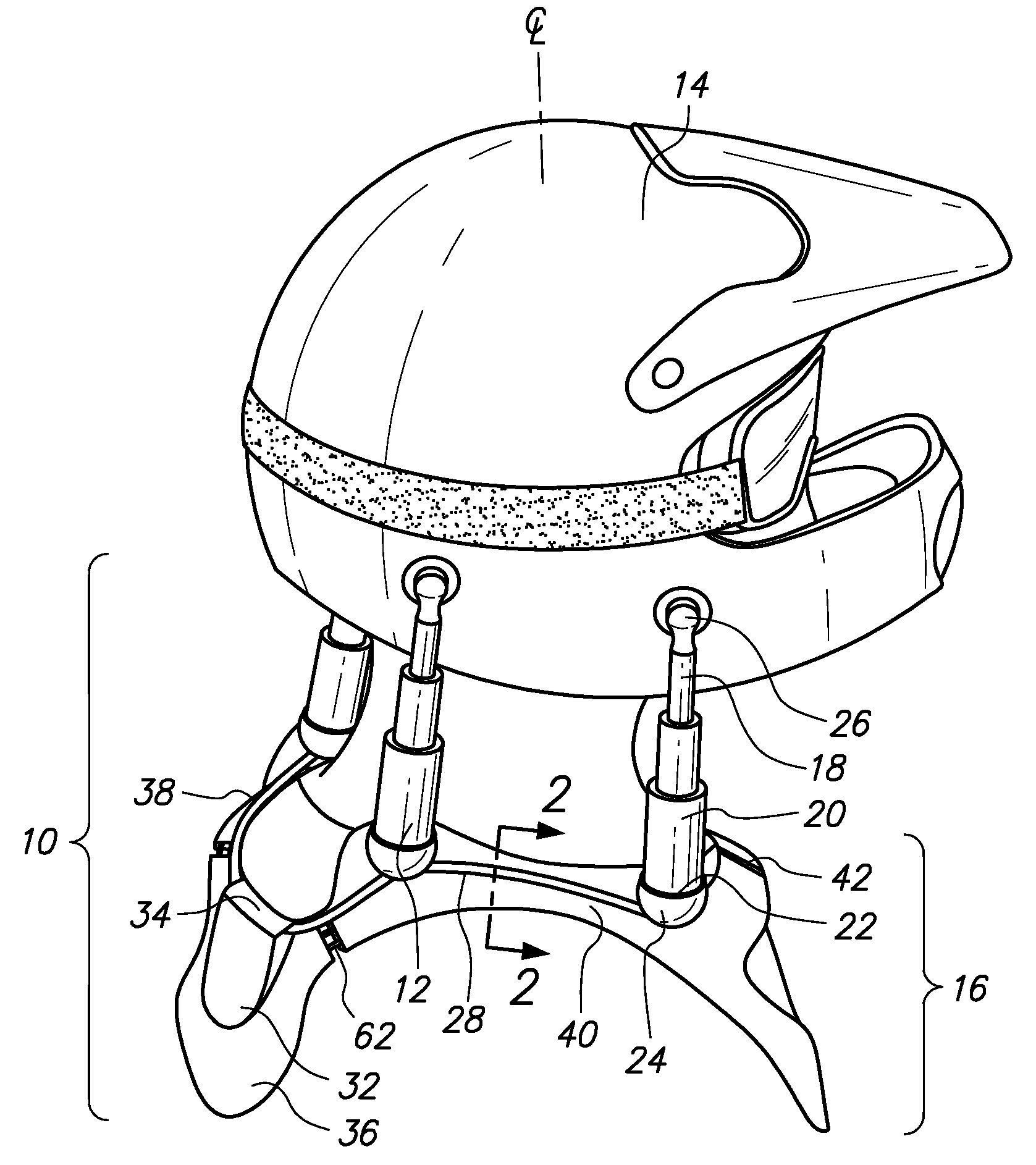
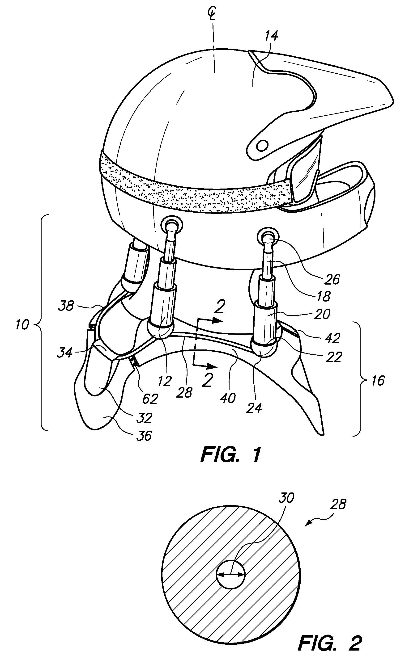
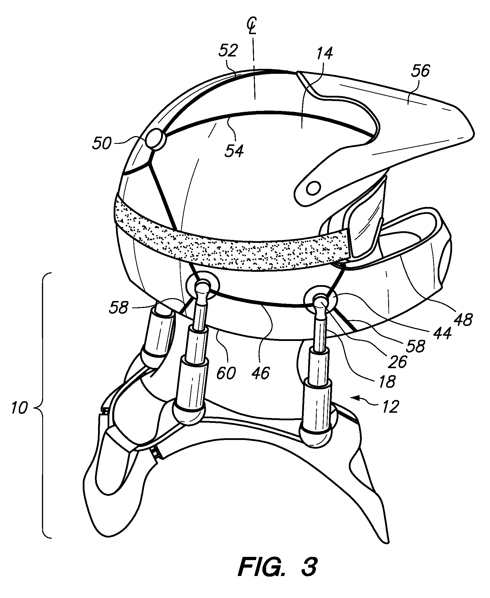
[0015]Referring now to the drawings, FIG. 1 is a rear perspective view of a first embodiment of the helmet suspension system 10. The helmet suspension system 10 may incorporate at least one piston or ram 12. Preferably, the helmet suspension system 10 may include four pistons 12, as shown in FIG. 1. The first piston 12 may be located in the front right area of the wearer. The second piston 12 may be located at the rear right area of the wearer. The third piston 12 may be located at the left rear area of the wearer. Lastly, the forth piston 12 (not shown) may be located around the front left area of the wearer. These pistons 12 limit movement of the helmet 14 upon experiencing extreme high velocity differential between the head and body of the wearer. However, during normal usage, the pistons 12 permit the wearer to rotate his / her head to engage in an activity (e.g., skiing, snowboarding, motocross, racecar driving, cycling, etc.). By way of example and not limitation, in motocross r...


PUM


Abstract

A head protection system is disclosed herein. The system may comprise a helmet having a rigid exterior shell and a padded interior. A shoulder cuff may be disposable over left and right shoulders of the wearer. A plurality of pistons may be attached to the helmet and the shoulder cuff. Each of the pistons may be fluidly connected to each other through a tube and ultimately to a reservoir. The tube may have a small inner diameter to provide resistance to movement of the pistons during rapid deceleration or acceleration of the helmet with respect to the wearer's body.

Description

CROSS-REFERENCE TO RELATED APPLICATIONS[0001]This application claims the benefits of U.S. Prov. Pat. App. Ser. No. 60 / 904,250, filed Mar. 1, 2007, the entire contents of which is expressly incorporated herein by reference.STATEMENT RE: FEDERALLY SPONSORED RESEARCH / DEVELOPMENT[0002]Not ApplicableBACKGROUND[0003]The present invention relates to a suspension system for a helmet to prevent neck and back injuries associated with a crash or other violent motion, but yet allow normal movement of the head during engagement of a physical activity.[0004]Activities that involve high speed, such as motocross racing, boating, flying all involve a risk of a high speed crash. Upon impact, the vehicle may rapidly decelerate to a halt but the participants may continue to travel at the vehicle's full speed. To prevent injury to the participants, participant restraint systems have been incorporated into vehicles. These participant restraint systems include, but are not limited to, seatbelts and harnes...

Claims


Application Information

Patent Timeline
IPC IPC(8): A41D13/00A42B3/00A41D27/26
CPCA42B3/0473A41D13/0512
Inventor CASTILLO, JAMES
Owner JDC RES & DEV CORP
Learn More