
Electronic toilet tank monitor utilizing a bistable latching solenoid control circuit

a control circuit and toilet tank technology, applied in water installations, flushing devices, constructions, etc., can solve the problems of increasing overall power consumption, inability to provide constant power source to existing toilets, and inability to include power source in bathroom facilities presently, so as to achieve low power consumption, reliable control of water level in toilet tanks, and faster acting

Inactive Publication Date: 2008-09-04
WOOD KURT E +1
View PDF24 Cites 4 Cited by
  • Summary
  • Abstract
  • Description
  • Claims
  • Application Information

AI Technical Summary

Benefits of technology

[0014]It is one object of the present invention to provide a refill mechanism that can reliably control water level in toilet tanks by controlling the inflow of water. Such a refill mechanism will receive with input signals provided by toilet tank level indicators appropriately positioned in the tank to signal when predetermined water levels exist. It is another object of the present invention to provide a toilet tank water control system that does not require a constant power supply. It is yet another object of the present invention to provide a mechanically reliable toilet tank water control system that can be operated at low power consumption levels. It is still another object of the present invention to provide smaller, faster acting self-latching solenoid actuated valves with low power consumption. It is also an object of the present invention to provide a bistable latching solenoid control circuit with minimal power requirements for actuating a water flow valve.
[0015]The present invention achieves many of the above-referenced advantages by utilizing a control system and control components which are specifically designed for power consumption concerns. More specifically, a bistable latching solenoid is utilized as the control for opening and closing a related water or fluid valve. By using a bistable latching solenoid, the valve can be opened and closed using small pulse signals from the control system. Most significantly, the control system is not required to continuously energize the solenoid, thus operating in a more energy efficient manner. In addition, the control circuitry is also specifically configured to conserve power and operate in an energy efficient manner.

Problems solved by technology

As such, existing toilets are not equipped with a constant power source.
Further, bathroom facilities do not presently include power source which would be convenient to the installed toilet (such as outlets in close proximity).
Maintaining the coil of the actuator in an energized state in order to maintain the actuator in a predetermined position increases overall power consumption.

Method used


Image

  • Electronic toilet tank monitor utilizing a bistable latching solenoid control circuit
  • Electronic toilet tank monitor utilizing a bistable latching solenoid control circuit
  • Electronic toilet tank monitor utilizing a bistable latching solenoid control circuit

Examples


Embodiment Construction

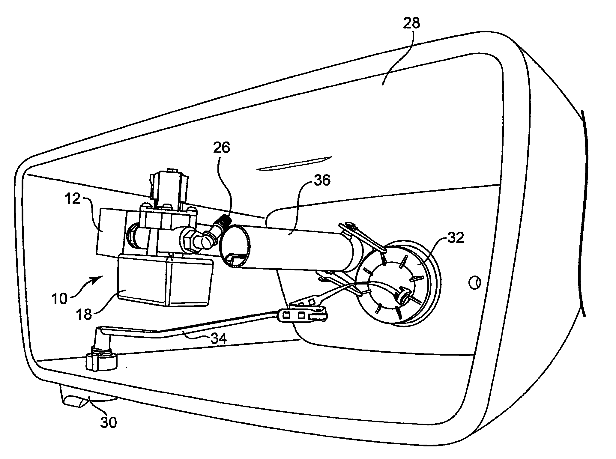
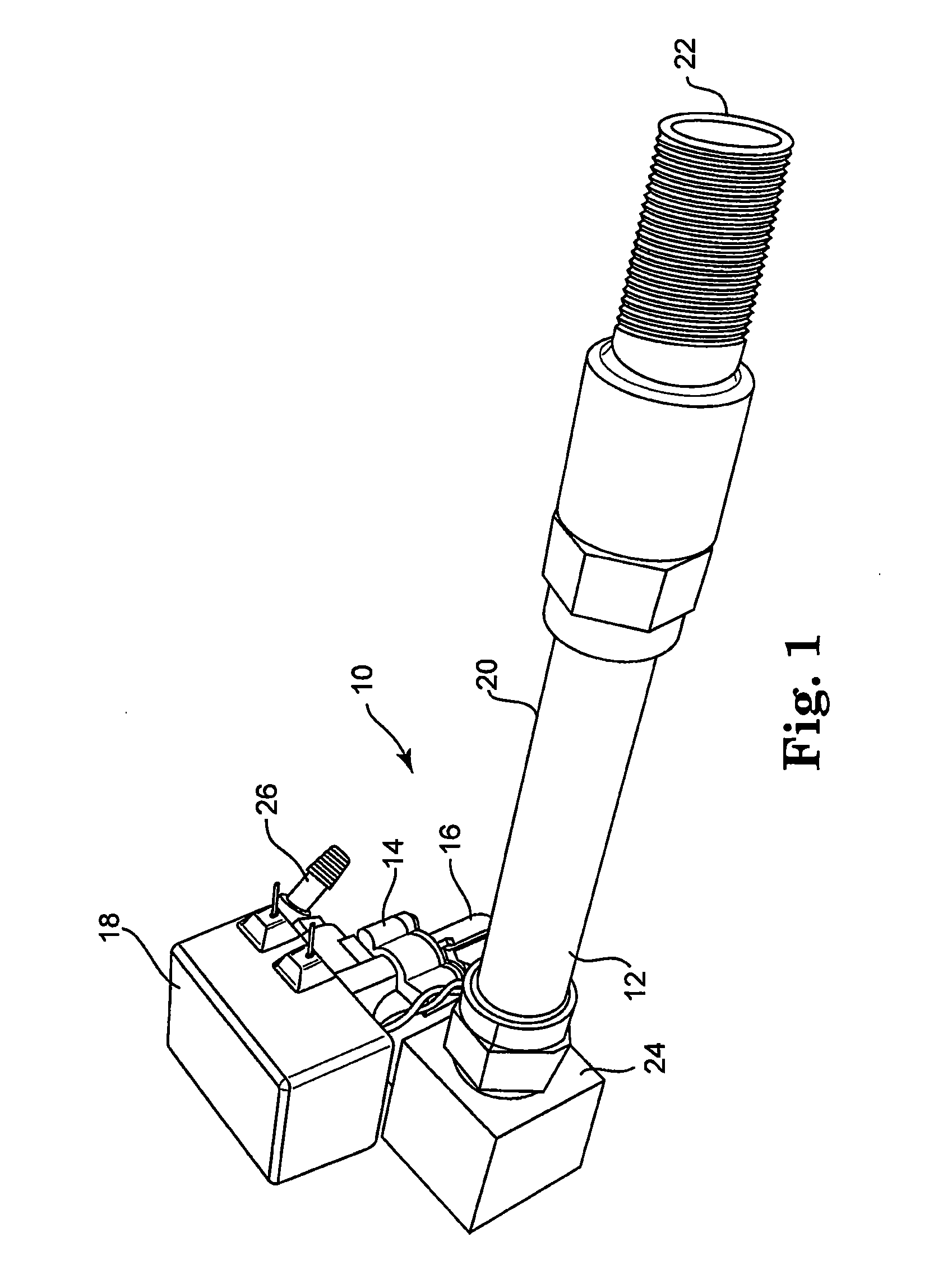
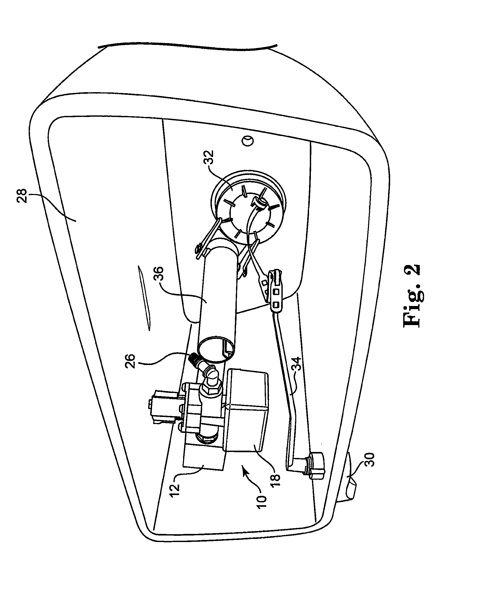
[0027]A toilet tank electronic monitor 10 in accordance with the present invention senses the presence or absence of water, i.e. the water level, in a toilet tank 28 (FIG. 2) using detection pins. This detection methodology is thus used to control at least one flow valve via a control circuit. Referring to FIG. 1, the toilet tank electronic monitor 10 in accordance with the present invention includes a fill tube assembly 12, a valve 14, a solenoid 16 and a control box 18. Fill tube assembly 12 includes a water conduit 20, a water inlet end 22 and a valve inlet end 24. While water conduit 20 is depicted as a generally tubular shape in the figures, those skilled in the art can appreciate that water conduit 20 can have various shapes and sizes to accommodate water feed to valve 14. A water source is connected to water inlet end 22 such that water is supplied from water inlet end 22 through water conduit 20 into valve inlet end 24. Water is provided to fill nozzle 26 only when valve 14 ...


PUM


Abstract

A fluid control circuit system is capable of maintaining fluid within a fluid tank at a desired level using electronic sensors and control circuitry, where the control circuitry and actuators are configured for low power consumption, thus allowing operation to be powered by a self contained internal power supply. To provide appropriate fluid control, the system includes a fluid sensor indicating if fluid is at a predetermined level, control circuitry attached to the fluid sensor, a latching solenoid attached to the control circuitry and also attached to a fluid control valve, and an internal power supply to power all electrical components.

Description

[0001]This application claims the benefit of Provisional Application No. 60 / 892,359 filed Mar. 1, 2007.BACKGROUND OF THE INVENTION[0002]1. Field of the Invention[0003]The present invention relates to an electronic toilet tank monitor utilizing a bistable latching solenoid control circuit to operate solenoid actuated valves. More generally, the present invention relates to a control circuit for controlling bistable latching solenoids used to control actuated valves.[0004]2. Discussion of the Related Art[0005]Certain common flush toilets include a water tank positioned above a toilet bowl. The tank holds enough water so that when the water in the tank is released into the bowl fast enough, the water will activate a siphon in the drain line of the toilet. In addition to requiring a certain volume of water, it is critical that the water is released into the bowl within a relatively small time frame, generally about 3 seconds in order to activate the siphon to flush the water out of the ...

Claims


Application Information

Patent Timeline
Patent Type & Authority Applications(United States)
IPC IPC(8): E03D5/00
CPCE03D5/10E03D1/36
Inventor WOOD, KURT E.BLAKESLEE, MERRILL G.
Owner WOOD KURT E
Learn More