Electrical power supply for an aircraft

a technology for aircraft and power supply, applied in the direction of electric generator control, electric device control, dynamo-electric converter control, etc., can solve the problems of large weight and bulk that can become prohibitiv

Inactive Publication Date: 2008-09-04
HISPANO SUIZA SA
View PDF3 Cites 51 Cited by
  • Summary
  • Abstract
  • Description
  • Claims
  • Application Information

AI Technical Summary

Benefits of technology

[0027]An object of the invention is to provide an optimized architecture for an electricity power supply system for an aircraft enabling an engine zone of the aircraft to have sufficient electricity available for powering electrical loads integrated in the engine and in its surroundings, without being penalizing in terms of weight and bulk.

Problems solved by technology

A well-known architecture for an electricity power supply system of the kind described above has been found to be effective, but drawbacks arise when, as is the present trend, electricity is used instead of hydraulic power for actuating various pieces of equipment in the engine and its surroundings.
Conveying electricity from the network on board the airplane to loads external to the fuselage by means of electricity lines or harnesses that must be carefully secured and isolated leads to a large amount of weight and bulk that can become prohibitive when the number of pieces of electrical equipment for powering increases.

Method used


Image

  • Electrical power supply for an aircraft
  • Electrical power supply for an aircraft
  • Electrical power supply for an aircraft

Examples


Embodiment Construction

[0044]In the description below, the invention is applied to an airplane fitted with gas turbine engines. Nevertheless, the invention is applicable to airplanes fitted with engines of other types, and also to helicopters.

[0045]Elements in common between the architectures of the electrical power supply systems of FIGS. 1 and 2 have the same reference numerals.

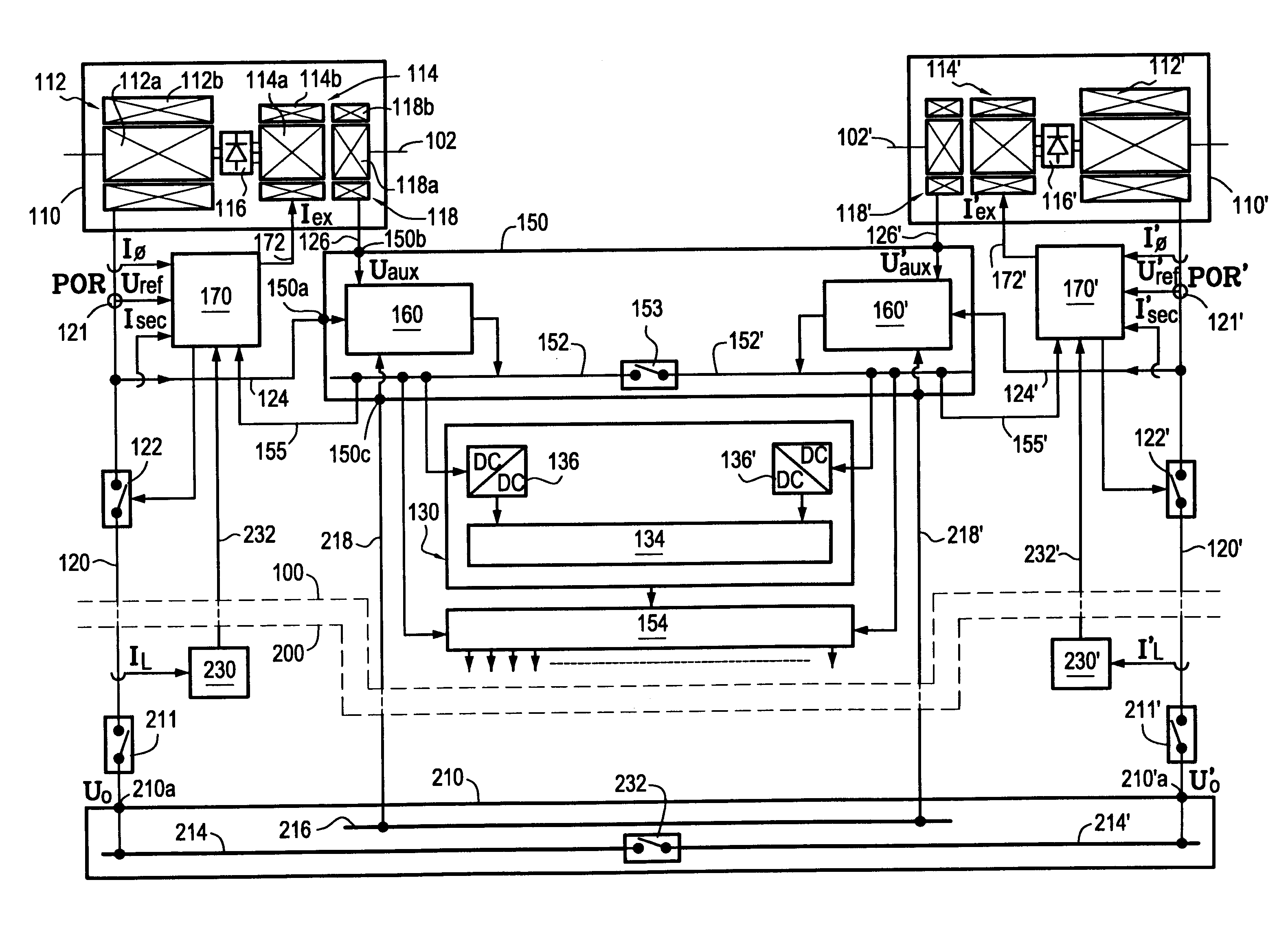
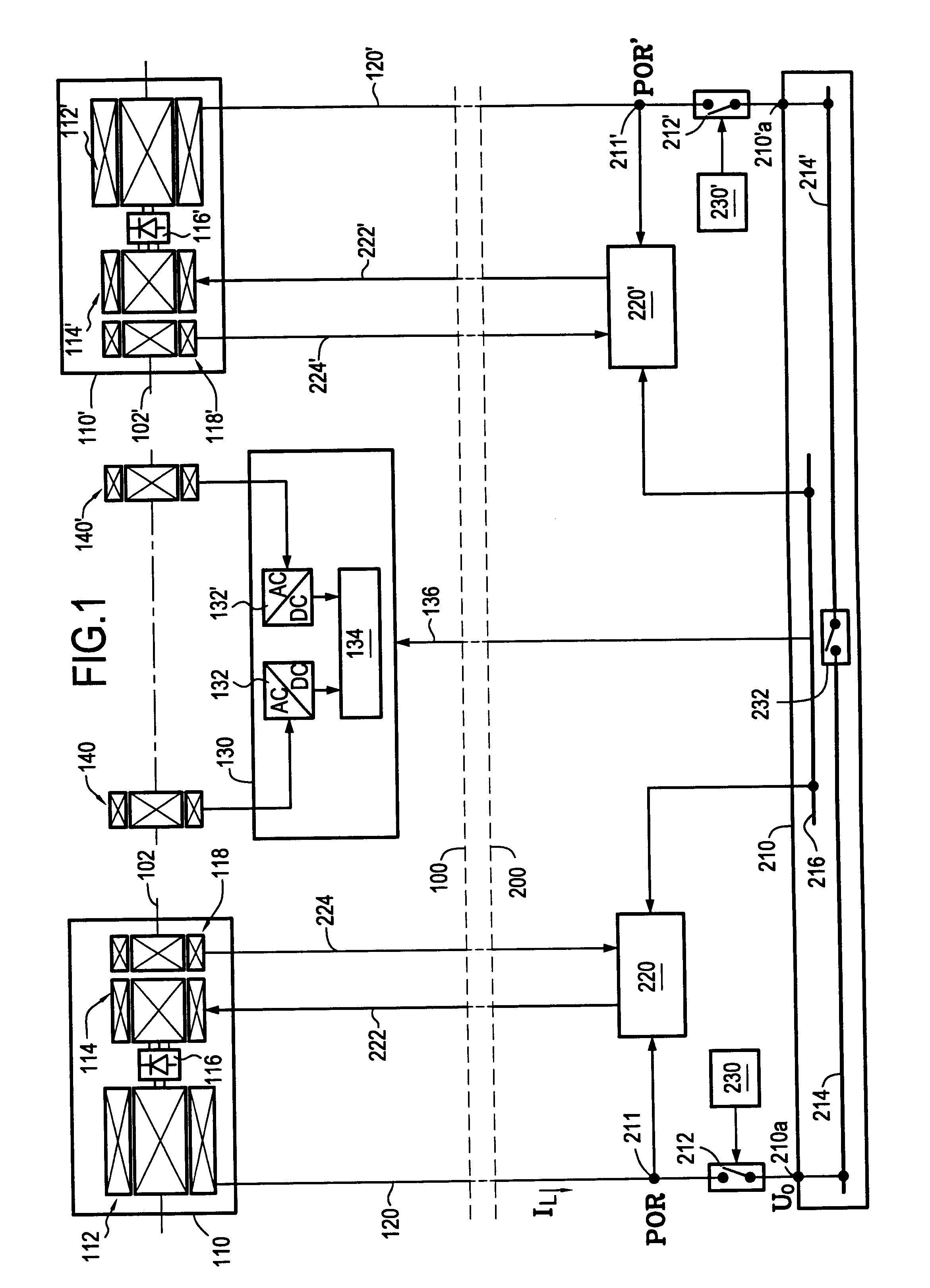
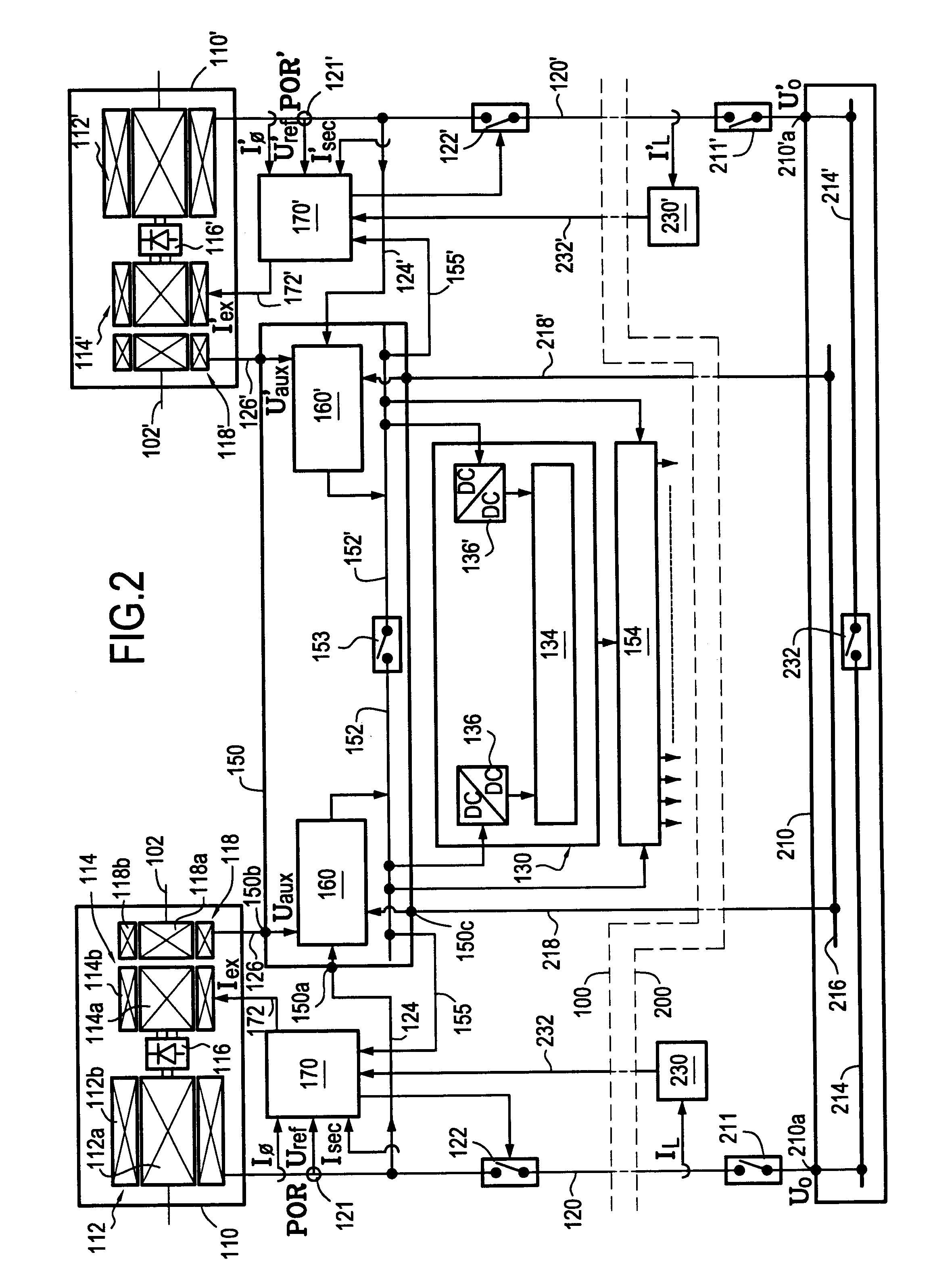
[0046]Thus, in FIG. 2, as in FIG. 1, dashed lines 100 and 200 represent respectively the frontier of the engine zone and the frontier of the fuselage zone.

[0047]In the engine zone, a main electrical generator 112 here formed by a synchronous generator, is mechanically coupled to the engine by mounting the rotor (primary magnetic circuit) 112a of the generator on a shaft 102 connected to an accessory gearbox mounted on a mechanical power takeoff coupled to a turbine shaft of the engine. The rotor 112a of the main generator 112 is fed with DC by being electrically connected to the rotor (secondary magnetic circuit) 114a of an excit...


PUM


Abstract

A main generator delivers an AC voltage to an electricity network on board an aircraft via a main line having at least one line contactor mounted therein, the voltage being regulated by a regulator. An engine electricity network delivers electricity to various loads situated in the zone of an engine fitted to the aircraft and to an engine control computer, the engine electricity network having a first fed input connected to the main electricity power supply line via a secondary electricity power supply line, upstream from the line contactor in order to receive directly electricity derived from the main generator without transiting via the electricity network on board the aircraft. The voltage regulator regulating the voltage delivered by the main generator may be situated in the engine zone and is powered by the engine electricity network.

Description

BACKGROUND OF THE INVENTION[0001]The invention relates to electrically powering aircraft and the engines fitted thereto.[0002]The field of application of the invention is more particularly that of airplanes fitted with gas turbine engines. Nevertheless, the invention is also applicable to airplanes fitted with other types of engine and more generally to various types of aircraft, i.e. both airplanes and helicopters.[0003]In an airplane, electricity is commonly generated by a main generator that is generally integrated in a starter / generator unit and that delivers an alternating voltage fed to an electricity network of the airplane via at least one line contactor. The airplane electricity network distributes electricity in the form of alternating current (AC) or direct current (DC) as needed for operating electrical loads situated in the fuselage zone and also in the engine zone.[0004]The AC voltage delivered by the main generator is regulated by a voltage regulator situated in the f...

Claims


Application Information

Patent Timeline
Patent Type & Authority Applications(United States)
IPC IPC(8): H02P9/00H02J3/38
CPCH02J3/12H02J2310/44
Inventor BERENGER, SERGE
Owner HISPANO SUIZA SA
Why Eureka
Try Eureka