Magnetic detector and method for making the same

a magnetic detector and fixed resistor technology, applied in the field of noncontact magnetic detectors, can solve the problems of inability to make the fixed resistor and the magnetoresistive element in the same process, inability to form the fixed resistor having the same resistance r and tcr as the magnetoresistive element, and difficulty in forming the fixed resistor having the same resistance r and tcr. , to achieve the effect of reducing the size of the magnetic detector and being easy and adequa

Inactive Publication Date: 2008-09-04
ALPS ALPINE CO LTD
View PDF0 Cites 22 Cited by
  • Summary
  • Abstract
  • Description
  • Claims
  • Application Information

AI Technical Summary

Benefits of technology

[0026]According to this method, the magnetoresistive elements and the fixed resistors can have the same laminate structure, and the magnetization direction of the magnetic layer of the fixed resistor corresponding to the magnetic layer of the magnetoresistive element whose magnetization direction is variable can be adequately pinned. According to this invention, the resistance R and the temperature coefficient of resistance (TCR) of the fixed resistor can be easily and adequately adjusted to be equal to those of the magnetoresistive element, and a plurality of such magnetic detectors can be manufactured simultaneously. Furthermore, size reduction of the magnetic detectors can be achieved.

Problems solved by technology

In the case where a fixed resistor is to be formed by changing the order of stacking layers from that of the magnetoresistive element as described above, however, the fixed resistor and the magnetoresistive element cannot be made in the same process.
In other words, since the configuration of the multilayer structure of the magnetoresistive element is different from that of the fixed resistor, they cannot be made in the same process.
Therefore, the thickness of each layer varies between the fixed resistor and the magnetoresistive element, and it has been difficult to form a fixed resistor having the same resistance R and TCR as those of the magnetoresistive element.
The variation in resistance R and TCR between the magnetoresistive element and the fixed resistor causes a problem such as a variation in the midpoint potential between the magnetoresistive element and the fixed resistor connected in series.
However, producing a Joule heat of 300° C. or more requires significantly large electrical current.
There is also a problem in that the magnetic characteristics of the adjacent GMR patterns R1 and R3 will change by the Joule heat.
The magnetization direction of the magnetic layer of the fixed resistor is pinned by the bias magnetic field from the hard bias layer; however, there is a gap between the fixed resistor and the hard bias layer.

Method used


Image

  • Magnetic detector and method for making the same
  • Magnetic detector and method for making the same
  • Magnetic detector and method for making the same

Examples


Embodiment Construction

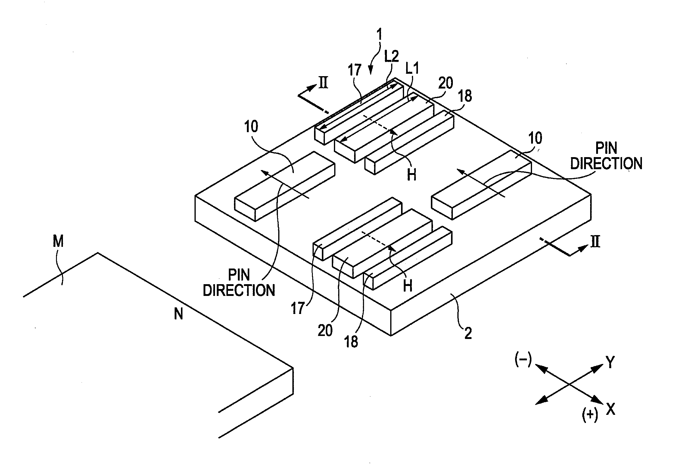
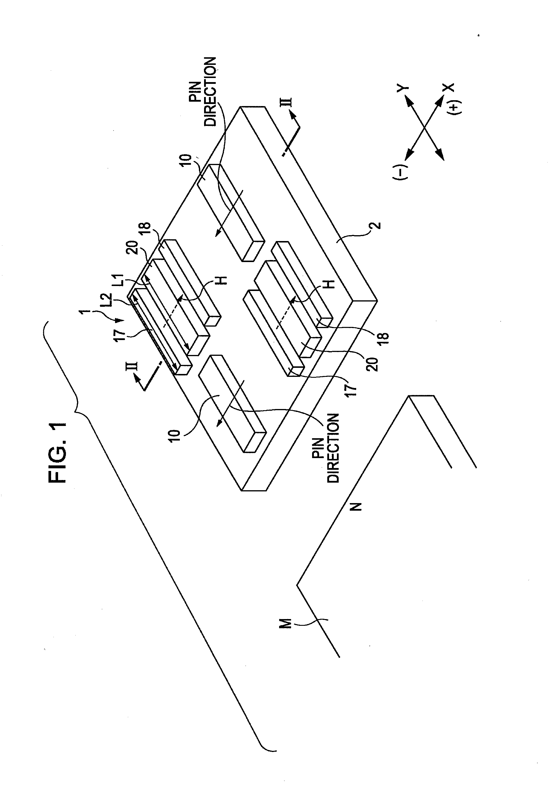
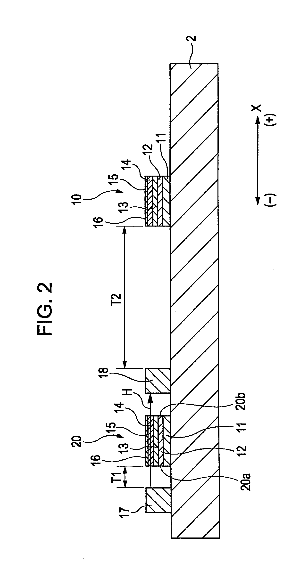
[0034]FIG. 1 is a perspective diagram of a magnetic detector according to an embodiment of the present disclosure. FIG. 2 is a cross-sectional view of the magnetic detector of FIG. 1 taken in a thickness direction along line II-II in FIG. 1, as viewed in the direction of the arrow. FIG. 3 is a circuit diagram of the magnetic detector of this embodiment. In the drawings, the X direction indicates the width direction, the Y direction indicates the length direction, and the X direction is orthogonal to the Y direction.

[0035]A magnetic detector 1 shown in FIG. 1 is an IC package in which magnetoresistive elements 10, fixed resistors 20, and an integrated circuit 19 (refer to FIG. 3) are integrated.

[0036]The magnetic detector 1 is not in contact with a magnetic field-generating member, a magnet M, for example. The electrical resistance of the magnetoresistive element 10 changes in response to the change in direction of the external magnetic field applied by the magnet M

[0037]The magnetor...


PUM

PropertyMeasurementUnit
thicknessaaaaaaaaaa
thicknessaaaaaaaaaa
temperatureaaaaaaaaaa

Abstract

A magnetic detector includes a magnetoresistive element and a fixed resistor that are constituted from identical laminates. Hard bias layers are disposed on two sides of the fixed resistor each with a gap therebetween. The magnetoresistive element includes a magnetic layer, magnetization direction of which is variable; the fixed resistor includes a magnetic layer corresponding to the magnetic layer of the magnetoresistive element; and the magnetization direction of the magnetic layer of the fixed resistor is pinned by a bias magnetic field from the hard bias layers

Description

CLAIM OF PRIORITY[0001]This application claims benefit of the Japanese Patent Application No. 2006-321657 filed on Nov. 29, 2006, which is hereby incorporated by reference in its entirety.BACKGROUND[0002]1. Field of the Invention[0003]The present invention relates to a non-contact magnetic detector incorporating a fixed resistor and a magnetoresistive element, and a method for making the non-contact magnetic detector.[0004]2. Description of the Related Art[0005]A giant magnetoresistive (GMR) element used in magnetic sensors has a basic layer configuration including an antiferromagnetic layer, a pinned magnetic layer, a nonmagnetic material layer, and a free magnetic layer. The pinned magnetic layer contacts the antiferromagnetic layer, and the pinned magnetic layer has its magnetization pinned in one direction by the exchange coupling magnetic field (Hex) generated between the pinned magnetic layer and the antiferromagnetic layer. The free magnetic layer is disposed at a position th...

Claims


Application Information

Patent Timeline
Patent Type & Authority Applications(United States)
IPC IPC(8): G01R33/09
CPCB82Y25/00Y10T29/4902G01R33/093
Inventor KURATA, KOJITOKUNAGA, ICHIRO
Owner ALPS ALPINE CO LTD
Why Eureka
Try Eureka