Driver-side floor structure of vehicle

a technology for driving positions and floor structures, applied in mechanical control devices, roofs, instruments, etc., can solve the problems of high production cost, difficult to ensure the installation space, and complex structure of required adjusting devices, and achieve the effect of simple structure and easy and adequate adjustment of driving postures

Inactive Publication Date: 2011-05-24
MAZDA MOTOR CORP
View PDF15 Cites 11 Cited by
  • Summary
  • Abstract
  • Description
  • Claims
  • Application Information

AI Technical Summary

Benefits of technology

In view of the above circumstances, it is an object of the present invention to provide a vehicle driver-side floor structure capable of adjusting a driving posture easily and adequately with a simple structure to allow a driver seated in a driver seat to adequately operate a control pedal.
In the aforementioned floor structure, the inclined surface portion is formed in at least a part of the heel-placement zone in such a manner as to rise relative to a surrounding area of the floor portion and have an upper surface extending obliquely upwardly and frontwardly. Thus, when the need arises, a driver seated in the diver seat can place his / her heel on the inclined surface portion and adjust a position of the heel to be placed on the inclined surface portion (heel-placement position) to allow a ball region of the driver to be brought into contact with the depressing point of the control pedal, while keeping each of an angle of an ankle region and an inclination angle of a sole of the driver, at an adequate value. This provides an advantage of being able to prevent the occurrence of difficulty in delicately perform a pedal-depressing operation, due to a situation where a heel of an operating-foot of the driver is spaced apart from a floor surface during the pedal-depressing operation, and further prevent the occurrence of difficulty in quickly operating the control pedal due to a situation where the angle of the ankle region or the inclination angle of the sole is largely deviated from the adequate value.

Problems solved by technology

However, in the driving posture adjusting system comprising the seat-position adjusting means adapted to adjust a longitudinal position of a driver seat and a vertical position and an inclination angle of a seat cushion, and the floor-panel position adjusting means adapted to adjust a vertical position of a movable floor, there are problems, such as structural complexity in required adjusting devices, and high production cost.
This involves a problem, such as difficulty in sufficiently ensuring the installation space.
Thus, it is extremely difficult to adjust all the position and the angle of the driver seat and the vertical position of the movable floor to respective desired positions.
However, this point is not considered in the Patent Document 2 at all, and the operability of the foot-operated pedal is likely to become worse due to the presence of the pedal base.

Method used


Image

  • Driver-side floor structure of vehicle
  • Driver-side floor structure of vehicle
  • Driver-side floor structure of vehicle

Examples


first embodiment

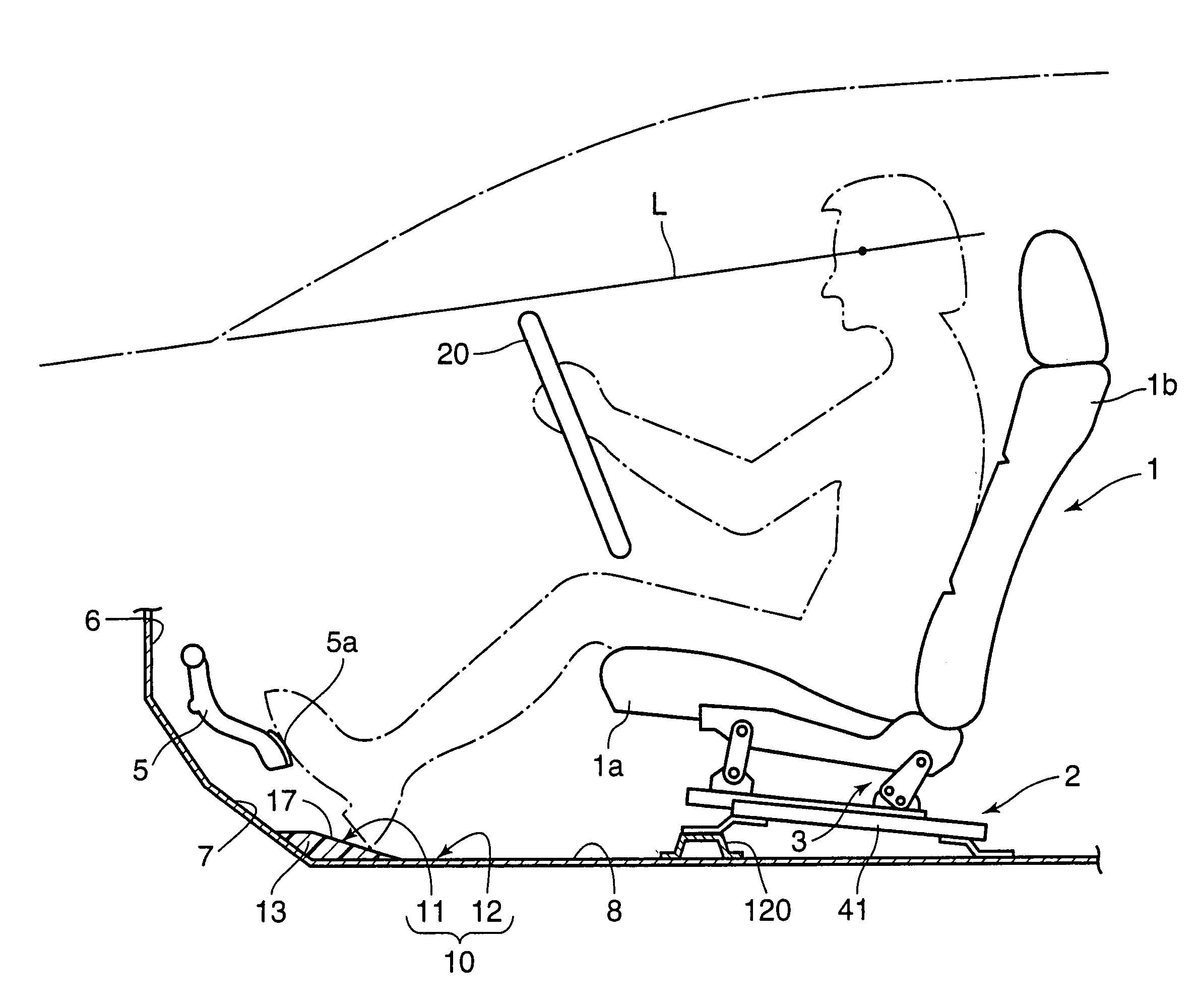
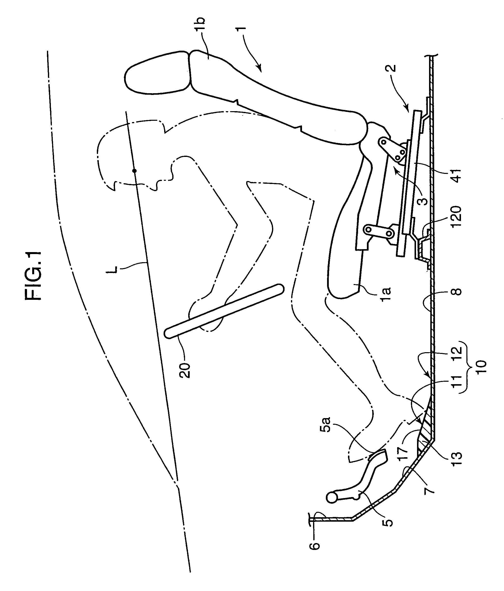
FIGS. 1 to 5 show a floor structure on a driver side of a vehicle, according to the present invention. This vehicle is equipped with a seat adjustment mechanism which includes a longitudinal-position adjustment mechanism 2 adapted to slidingly displace a seat cushion 1a of a driver seat 1 arranged inside a passenger compartment thereof to adjust a position of the driver seat 1 in a frontward-rearward (i.e., longitudinal) direction of a vehicle body (or vehicle), and a tilt-angle adjustment mechanism 3 adapted to adjust a tilt angle of the seat cushion 1a. Further, two control pedals consisting of a brake pedal 4 and an accelerator pedal 5 each adapted to be depressedly operated by a driver seated in the driver seat 1 are arranged side-by-side in a rightward-leftward (i.e., widthwise or lateral) direction of the vehicle body.

The vehicle body comprises a dash panel 6 partitioning between an engine compartment and the passenger compartment, a kick-up portion 7 continuously extending fr...

second embodiment

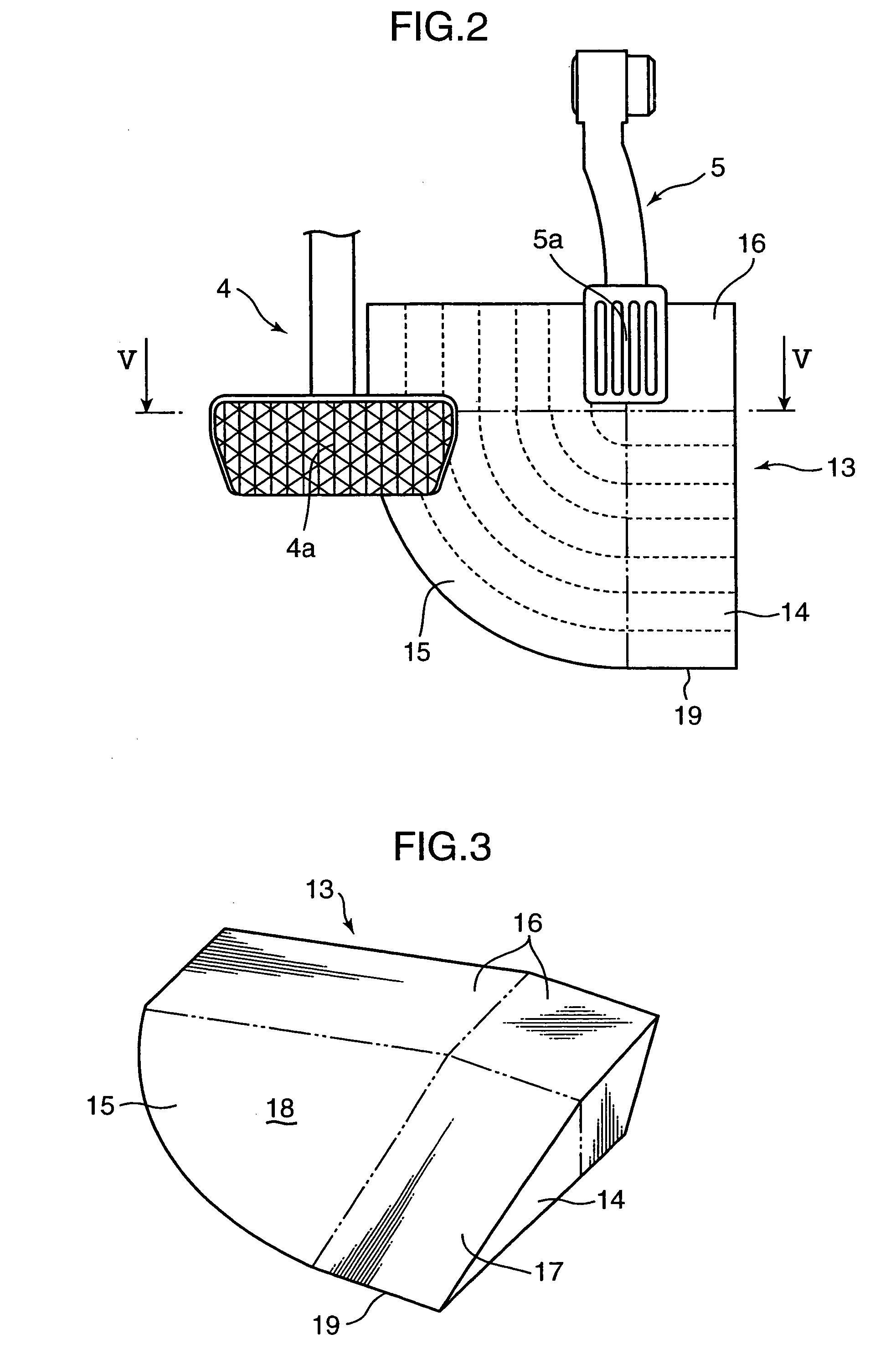
Further, as shown in the second embodiment, the sector-shaped portion 15b extending from the inclined surface portion 14a and having an upper surface with the same inclination angle as that of the inclined surface portion 14a is formed on a left side of the inclined surface portion 14a. In this case, even when the short person S seated on the driver seat 1 operates the brake pedal 4 by his / her left foot, a braking operation can be performed while placing the heel on the sector-shaped portion 15a.

FIGS. 18 to 21 show a vehicle driver-side floor structure according to a third embodiment of the present invention. In the third embodiment, in a floor structure on a driver side of a vehicle where a control pedal includes a brake pedal 4 and an accelerator pedal 5 on a right side of the brake pedal 4, a pad member 21 comprises a first heel-placement portion 22 located rearward of the brake pedal 4, and a second heel-placement portion 23 located rearward of the accelerator pedal 5, and a co...

third embodiment

As above, in the third embodiment, the first heel-placement portion 22 located rearward of the brake pedal 4, and the second heel-placement portion 23 located rearward of the accelerator pedal 5, make up the inclined surface portion which rises relative to a surrounding region of the floor portion and having the upper surface extending obliquely upwardly and frontwardly. This also provides an advantage of being able to adjust a driving posture readily and adequately with a simple structure so as to allow a driver seated in the driver seat 1 to adequately operate the control pedal including the brake pedal 4 and the accelerator pedal 5.

Specifically, as for three subjects having body heights falling within the range of 150 to 159 cm, six subjects having body heights falling within the range of 160 to 169 cm, and three subjects having body heights falling within the range of 170 to 179 cm, a heel-placement position during a normal heel-placement position in top plan view was checked. F...


PUM


Abstract

A floor structure on a driver side of a vehicle where a control pedal, such as a brake pedal, adapted to be depressedly operated by a driver seated in a driver seat arranged at a front of a passenger compartment. The floor structure has a heel-placement zone which is provided on an approximately horizontal floor portion located rearward of a depressing point of the control pedal, and formed to have a frontward region adapted to allow a short person seated in the driver seat place his / her heel thereon and a rearward region adapted to allow a tall person seated in the driver seat place his / her heel thereon. The heel-placement zone includes an inclined surface portion formed in at least part thereof in such a manner as to rise relative to a surrounding area of the floor portion and has an upper surface extending obliquely upwardly and frontwardly. The floor structure can adjust a driving posture easily and adequately with a simple structure to allow a driver seated in the driver seat to adequately operate the control pedal.

Description

CROSS REFERENCE TO RELATED APPLICATIONThis application claims the benefit of Japanese Application No(s). 2008-53870, 2008-53871, and 2008-53872, filed Mar. 4, 2008, in the Japanese Patent Office, the disclosures of which are incorporated herein by reference.BACKGROUND OF THE INVENTION1. Field of the InventionThe present invention relates to a floor structure on a driver side of a vehicle where a control pedal adapted to be depressedly operated by a driver seated in a driver seat is arranged at a front of a passenger compartment.2. Description of the Background ArtHeretofore, there has been known a driving posture adjusting system for a vehicle, which comprises seat-position adjusting means adapted to adjust a position of a seating surface of a seat, floor-panel position adjusting means adapted to adjust a vertical position of a floor panel (movable floor) for allowing a passenger who intends to operate a pedal to place his / her foot thereon, and manually-operated driving-posture adju...

Claims


Application Information

Patent Timeline
Patent Type & Authority Patents(United States)
IPC IPC(8): B60N3/06
CPCB60N2/0232B60N2/067B60N2/1615B60N2/1695B60N3/06B60N2/164Y10T74/20918B60N2/02246
Inventor OHTSUBO, TOMONORIUEMURA, HIROKITAKEDA, YUSAKUIWAMOTO, ASAMI
Owner MAZDA MOTOR CORP
Why Eureka
Try Eureka