Field device system and field device system diagnosing method

Inactive Publication Date: 2008-09-04
YOKOGAWA ELECTRIC CORP
View PDF6 Cites 24 Cited by
  • Summary
  • Abstract
  • Description
  • Claims
  • Application Information

AI Technical Summary

Benefits of technology

[0050]According to the present invention, the field device system and the method of diagnosing the same, capable of predicting in advance occurrence of the failure such as open circuit, short circuit, or the like of the transmission

Problems solved by technology

Such system is exposed to the weather in open-air use.
However, in FIG. 20 and FIG. 21, when no packing is adequately provided to the wiring port, the rainwater, and the like soak into the inside of the field device, and sometimes the terminal portions are submerged.
When the terminal portions are submerged, the electrolysis of water is caused by a voltage applied to the terminal portions and thus sometimes a dangerous gas such as hydrogen, or the like is generated from the terminal portions.
Also, when a leakage current is further increased, in some cases the short circuit occurs between the terminal portions.
Therefore, such communication interference is caused that the host unit 6 cannot communicate with a plurality of field devices.
Therefore, such communication interference occurs that the host unit 6 cannot communicate with a plurality of field devices.
Also, the insulation degradation may occur because of the influence of the surrounding environment, and the transmission line is brought into the short circuit state.
When such abnormality of the transmission line occurs, the communication interference may be caused.
However, the user can know the failure of the transmission line based on the above operation of the wiring failure detecting portion and the wiring failure diagnosing manager only after such failure is caused.
Therefore, in some cases it is difficult to improve reliability of measurement, communic

Method used


Image

  • Field device system and field device system diagnosing method
  • Field device system and field device system diagnosing method
  • Field device system and field device system diagnosing method

Examples


first embodiment

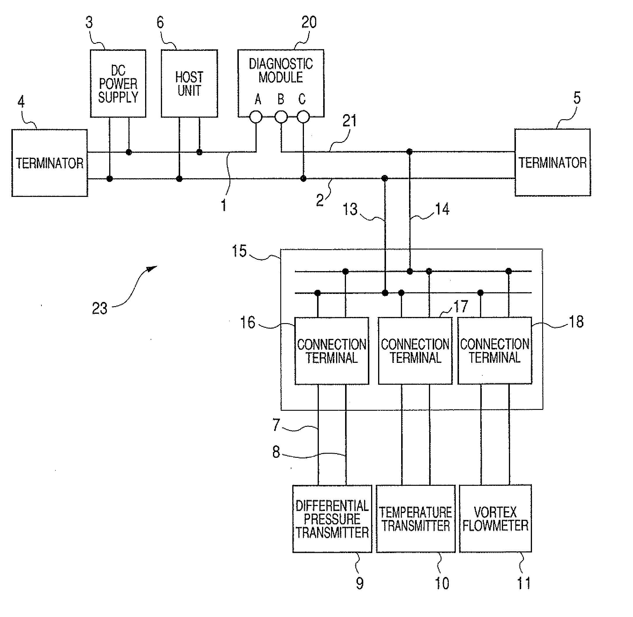
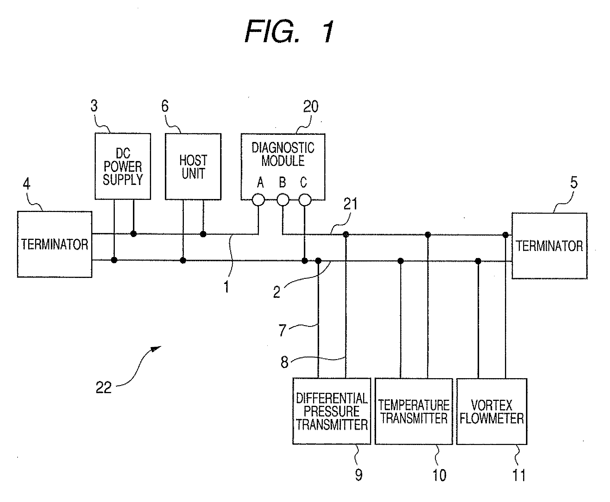
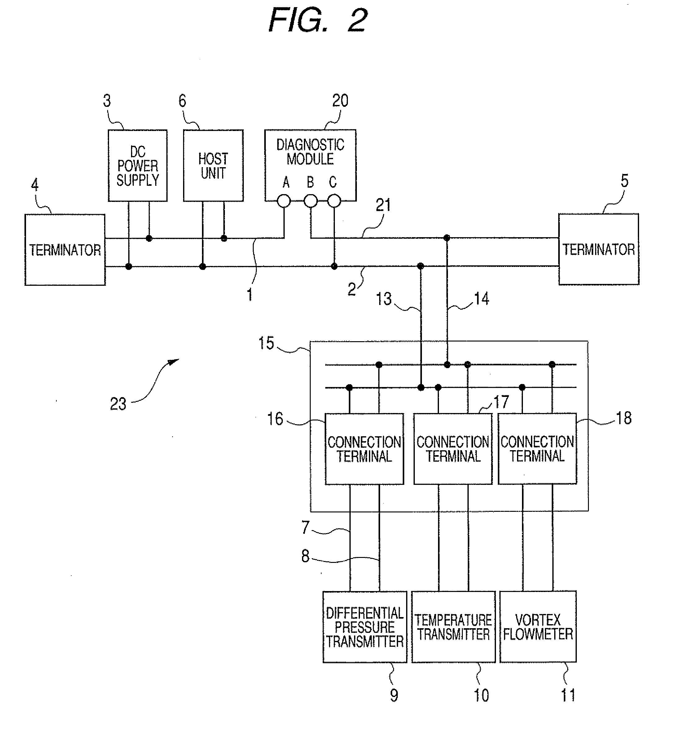
[0074]A first embodiment will be explained with reference to FIG. 1 to FIG. 3 hereunder. FIG. 1 is a field device system 22 showing a first embodiment of the present invention, and the same symbols are affixed to the same elements as those in FIG. 20 and their explanation will be omitted herein. FIG. 2 shows a field device system 23 when the multiple device connecting device 15 is employed in FIG. 1, and the same symbols are affixed to the same elements as those in FIG. 1 and FIG. 21 and their explanation will be omitted herein. FIG. 3 is a block diagram of a diagnostic module 20.

[0075]Then, explanation will be made on the assumption that the terminal portions of the differential pressure transmitter 9 are submerged.

[0076]In order to measure the transmission line current flowing through a plurality of field devices such as the differential pressure transmitter 9, the diagnostic module 20 is connected to the transmission lines 1, 2 connected between the DC power supply 3 and a plural...

second embodiment

[0093]A second embodiment of the diagnostic module 20 shown in a block diagram will be explained with reference to FIG. 4 hereunder. In FIG. 4, the same symbols are affixed to the same elements as those in FIG. 3 and their explanation will be omitted herein.

[0094]In FIG. 4, a communicating portion 34 is connected to the terminal A and the terminal C and the controlling portion 29. The communicating portion 34 receives the communication signal for calling upon the diagnostic module 20 to send the information from the host unit 6 via the transmission lines 1, 2, and transmits the information to the host unit 6 via the controlling portion 29. As the information, there are the output of the controlling portion 29, the measured value 33 of the current measuring portion 25, and the like. For example, data “1” is transmitted as the alarm output when the abnormality occurs in the transmission line (step S7), while data “0” is transmitted as the information when no abnormality occurs in the ...

third embodiment

[0096]A third embodiment of the diagnostic module 20 shown in a block diagram will be explained with reference to FIG. 5. In FIG. 5, the same symbols are affixed to the same elements as those in FIGS. 3, 4 and their explanation will be omitted herein.

[0097]In FIG. 5, the diagnostic module 20 has a timer 35 and a storing portion 36. The timer 35 contains time information of current date and time. The storing portion 36 is connected to the output of the current measuring portion 25, the output of the timer 35, and the controlling portion 29.

[0098]The storing portion 36 stores the time information of the timer 35 and the measured value 33 of the current measuring portion 25, as the information that the diagnostic module 20 has. For example, the data is stored in the storing portion 36 between step S5 and step S6 in FIG. 9. The alarm output data may be stored in the storing portion 36 via the controlling portion 29 in step S7 and step S9.

[0099]In response to the information requesting s...


PUM


Abstract

A field device system having a transmission line, includes a diagnostic module that detects whether or not a failure of the transmission line is present.
Also, the diagnostic module has at least one measuring portion for measuring electric characteristics of the transmission line, and the like.

Description

TECHNICAL FIELD[0001]The present disclosure relates to a field device system connected to a transmission line and, more particularly, to detect and diagnose a failure such as short-circuit of the transmission line, or the like.[0002]Also, the present disclosure relates to a failure diagnosis of a field device system and, more particularly, a field device system and a method of diagnosing the same for improving reliability of communication, etc. in the field device system against a failure such as open circuit, short circuit, or the like of the transmission line.RELATED ART[0003]For example, in the plant instrumentation, the system in which the host unit and the field devices are connected via the transmission lines is often employed. Such system is exposed to the weather in open-air use. Thus, rainwater, and the like soak into the inside of the field device, and sometimes the terminal portions are submerged to cause the short circuit between terminal portions.[0004]A configuration o...

Claims


Application Information

Patent Timeline
IPC IPC(8): G08B29/06
CPCG05B2219/21162G05B19/0428
Inventor TAKEUCHI, MAKOTO
Owner YOKOGAWA ELECTRIC CORP
Why Eureka
Try Eureka