Resistance balance circuit

a resistance balance and circuit technology, applied in the direction of instruments, static indicating devices, electroluminescent light sources, etc., can solve the problems of high cost of driving each circuit, parallel connection of leds, complicated process, etc., and achieve the effect of enhancing the homogeneity of current passing electronic components and lack of luminance homogeneity

Inactive Publication Date: 2008-09-04
IND TECH RES INST
View PDF9 Cites 3 Cited by
  • Summary
  • Abstract
  • Description
  • Claims
  • Application Information

AI Technical Summary

Benefits of technology

[0016]A resistance balance circuit of the present invention enhances homogeneity of current passing electronic components, wherein at least two electronic components aligned in a column matrix or a row matrix are electrically connected to one another. The input end for entry of current passing the electronic components in the matrix and the output end for exit of current passing the electronic components in the matrix are disposed at opposite corners of the matrix. The routes f...

Problems solved by technology

Although the known problem of tilted resistance balance in the LED array structure can be solved with U.S. Pat. No. 5,598,068, high costs are incurred for driving each circuit 13 having a plurality of series-connected LEDs by means of a single constant current source 12.
Moreover, semiconductor technology-based fabrication of light source facilities equipped with the LED array structure requires the current mirror 10 and constant current source 12 and thereby involves a complicated process.
However, to enable homogeneity of the pa...

Method used


Image

  • Resistance balance circuit
  • Resistance balance circuit
  • Resistance balance circuit

Examples


Embodiment Construction

[0025]The following specific embodiments are provided to illustrate the present invention. Persons skilled in the art can readily gain insight into other advantages and features of the present invention based on the contents disclosed in this specification.

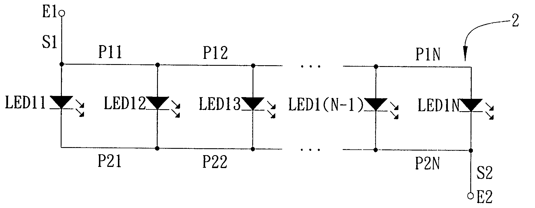
[0026]FIG. 4A is a schematic view showing the first preferred embodiment of a resistance balance circuit of the present invention. FIG. 4B is a schematic view showing the second preferred embodiment of a resistance balance circuit formed with a plurality of series-connected light emitting diode array structures shown in FIG. 4A. The resistance balance circuit is applicable to at least two electronic components aligned in a row matrix so as to achieve circuit resistance balance in the routes for current passing the electronic components in the row matrix structure. Advantages are namely homogeneity of current passing the electronic components in every route, cost reduction, and process streamlining. The electronic components of the...


PUM


Abstract

This invention discloses a resistance balance circuit including: at least two electronic components aligned in a row matrix, connected to one another in parallel, thereby forming a row matrix structure; an input end disposed at one end of the row matrix structure and configured for entry of current passing the electronic components in the row matrix structure; and an output end disposed diagonally opposite to the input end in the row matrix structure and configured for exit of the current passing the electronic components in the row matrix structure, wherein routes for the current passing the electronic components from the input end to the output end are equal in length, and thus the same current passes the electronic components in the matrix structure.

Description

BACKGROUND OF THE INVENTION[0001]1. Field of the Invention[0002]The present invention relates to resistance balance circuits, and more particularly, to a resistance balance circuit aligned in a column matrix or a row matrix and configured for electrical connection between at least two electronic components with a view to achieving homogeneity of current passing the electronic components.[0003]2. Description of the Prior Art[0004]Owing to their advantages over conventional light sources, namely being highly efficient, long-lived and durable, light emitting diodes (LEDs) are widely used in light source facilities, such as traffic signal lamps, vehicle lamps, desk lamps, street lamps, billboards, and liquid crystal display backlight modules.[0005]The LED-based light source facilities require use of plenty LEDs, resulting in a LED array structure 1 shown in FIG. 1. Characteristics are different from LED to LED, so are routes provided for current to pass LEDs in the LED array structure, ...

Claims


Application Information

Patent Timeline
IPC IPC(8): G09G3/32
CPCH05B33/0803H01L2224/05554H01L2224/48091H01L2224/48247H05B45/35H01L2924/00014
Inventor HUANG, TIEN-FUHU, KUO-CHANGHUA, SHIH-HAO
Owner IND TECH RES INST
Why Eureka
Try Eureka