

Prevention of re-use of a medical device
a medical device and reuse technology, applied in the field of disposable medical devices, can solve the problems of device not being attached to a handpiece assembly, risk of transmitting infectious diseases, and warnings being overlooked
- Summary
- Abstract
- Description
- Claims
- Application Information
AI Technical Summary
Benefits of technology
Problems solved by technology
Method used
Image

Examples
first embodiment
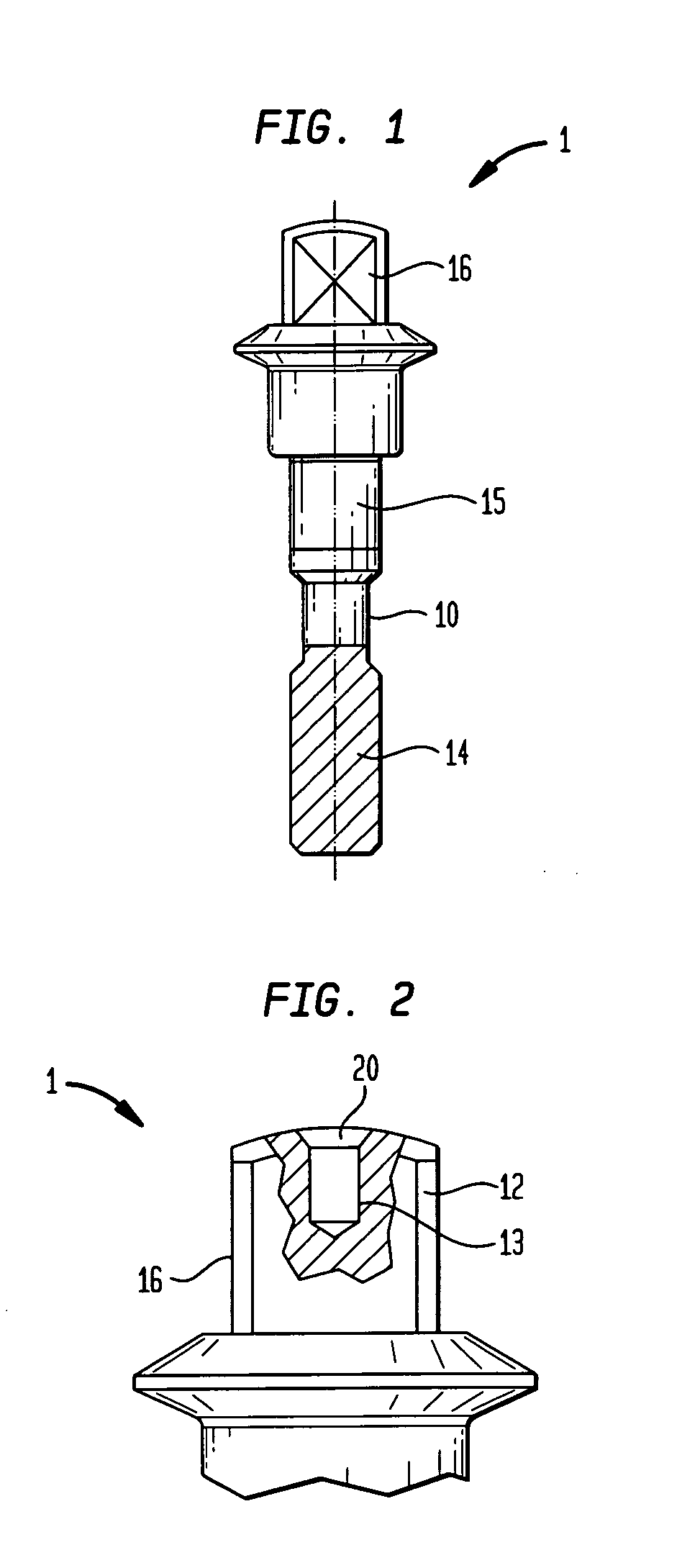
[0023]FIG. 1 shows such a central shaft 10 as usable in an articulation device according to FIG. 3 in detail. Essentially the central shaft of FIG. 1 comprises a threaded section 14, a cylindrical section 15 and a head portion 16. The only mandatory element of this element 10 is the head section 16, i.e. a section which is visible from outside or is at least in contact with the outer surroundings.
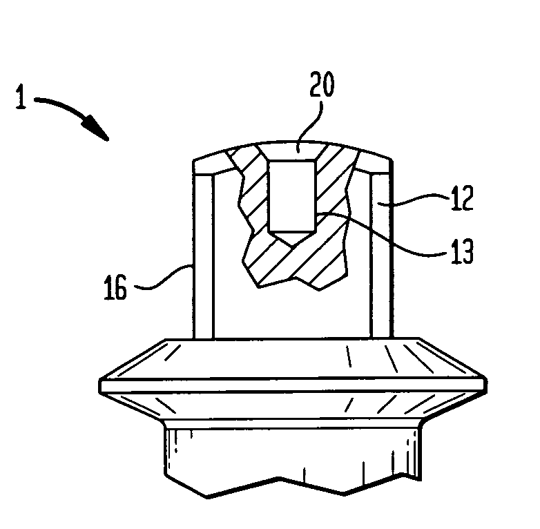
[0024]FIG. 2 shows the head portion 16 according to the first embodiment of the present invention. The head portion 16 comprises the head 12, which is provided with an opening 13 that extends along the central axis of the central shaft. The opening 13 is preferably a center bore with a diameter that is clearly recognisable by medical personnel. Preferably the diameter is between 1 mm and 5 mm. However larger diameters are also possible because they increase the visibility.
[0025]An insert 20 is introduced into the opening 13. The insert 20 is preferably made out of a material having a meltin...
second embodiment
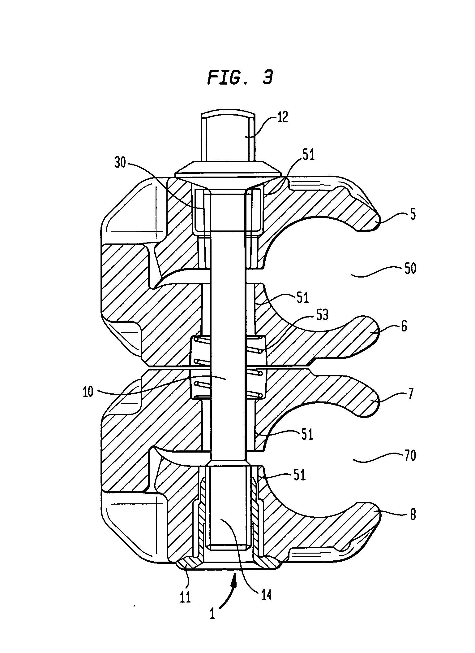
[0031]FIG. 3 shows the disposable articulation in combination with a rectangular insert 30 according to the present invention.
[0032]In this embodiment one of the jaws, here jaw 5, comprises an opening intended to receive the rectangular insert 30.
[0033]An example of the rectangular insert 30 is shown in a perspective view in FIG. 5. Thereby the rectangular insert 30 has preferably a cuboid shape and comprises an opening 31 for receiving the central shaft 10.
[0034]The rectangular insert 30 is placed in the opening 51. Thereby the central axes of the opening 51 and of the opening 31 are preferably coaxial. The central shaft 10 is then introduced into the opening 51 and 31. The insert 30 is within a cavity inside jaw 5 and does not rotate, when the screw function of the shaft is activated, i.e. the clamp is clamping a rod.
[0035]The rectangular insert is preferably made out of the same material as the insert of the first embodiment.
[0036]In case the disposable articulation will be heate...
third embodiment
[0040]Before referring to these drawings in detail, it is referred to FIG. 9, showing a central shaft in combination with an element according to the present invention. The element here is a shape memory alloy or polymer bracket 40 or a wire being able to take in two different positions or geometries. A first starting position describes the geometric shape at room temperature (FIG. 9). A second position (FIG. 10) describes the geometric shape after the temperature has crossed a (higher) threshold temperature once.
[0041]FIG. 11 shows a bracket 40 according to the first initial position. The bracket 40 comprises a first leg 41 and a second leg 42. The second leg 42 is arranged angular to the first leg 41 and especially forms an acute angle. The first leg 41 of the wire like bracket is introduced into a corresponding recess 43 within the central shaft 10. The position of the recess 43 is slightly offset to a radial line through the center of the shaft 10. The second leg is bent towards...
PUM
 Abstract
Description
Claims
Application Information