Machining time predicting apparatus of numerically controlled machine tool

a technology of numerical control and machine tool, which is applied in the direction of program control, total factory control, instruments, etc., can solve the problem of taking a lot of processing time of the technique, and achieve the effect of enhancing the precision of the accurate prediction of the machining time, and shortening the machining tim

Active Publication Date: 2012-05-03
FANUC LTD
View PDF12 Cites 21 Cited by
  • Summary
  • Abstract
  • Description
  • Claims
  • Application Information

AI Technical Summary

Benefits of technology

[0015]The speed calculating unit is a unit that calculates the speed in the tangential direction of the segment from a starting point to a terminal of the segment. The speed calculating unit can include a terminal speed calculating unit that determines the speed at the terminal of each segment based upon at least one of a speed difference, acceleration difference, and a jerk difference between the adjacent segments, the curvature of the tool path, and the number of the segments used for the calculation of the speed; a tangential-direction acceleration calculating unit that sets the acceleration in the tangential direction of the segment as the maximum value by which a component in a direction of an axis driven by the NC command does not exceed the maximum acceleration of each axis; an upper limit speed calculating unit that compares a value obtained by multiplying the designated speed by a predetermined coefficient with a predetermined value based upon the curvature of the tool path so as to decide the upper limit speed of the segment; and a speed curve calculating unit that calculates a speed curve, which is a speed in the tangential direction of the segment, by using the acceleration in the tangential direction obtained by the tangential-direction acceleration calculating unit, in such a manner that the speed does not exceed the upper limit speed decided by the upper limit speed calculating unit and the speed at the terminal of the segment does not exceed the speed obtained by the terminal speed calculating unit. With this, the machining time can accurately be predicted, even when the speed control due to the speed, acceleration, jerk, and the curvature of the tool path is made.
[0016]The speed curve calculating unit selects one of a plurality of speed calculating units prepared beforehand, and can calculate the speed curve by the selected calculating unit. With this, the machining time can be shortened according to the balance of the precision in the predicted value of the processing time.
[0017]According to the configuration described above, the present invention can provide a predicting apparatus of a machining time by a numerically controlled machine tool, which can enhance a precision of the prediction of the machining time and can shorten the time for predicting the processing time.

Problems solved by technology

Therefore, this technique takes much processing time.

Method used


Image

  • Machining time predicting apparatus of numerically controlled machine tool
  • Machining time predicting apparatus of numerically controlled machine tool
  • Machining time predicting apparatus of numerically controlled machine tool

Examples


Embodiment Construction

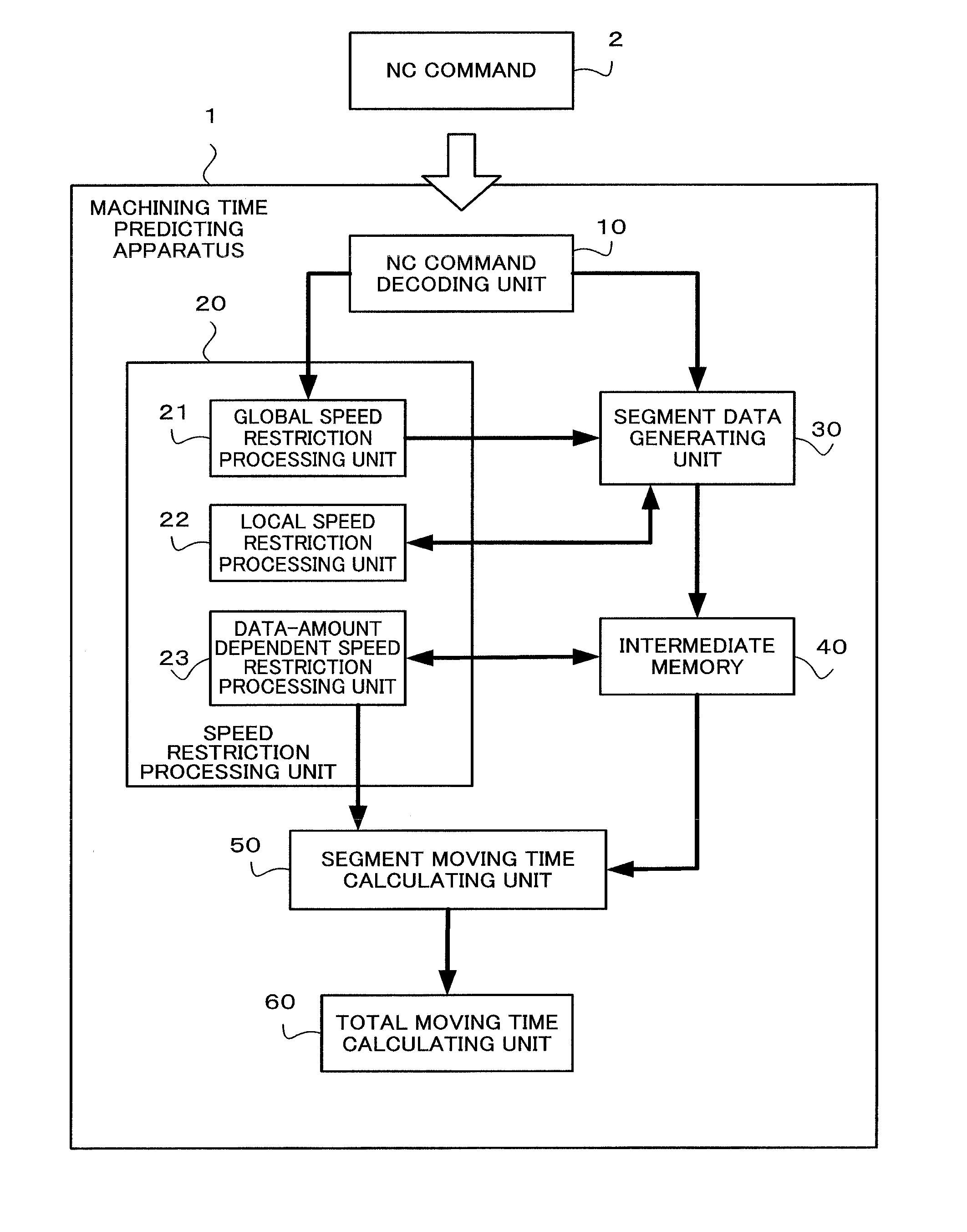
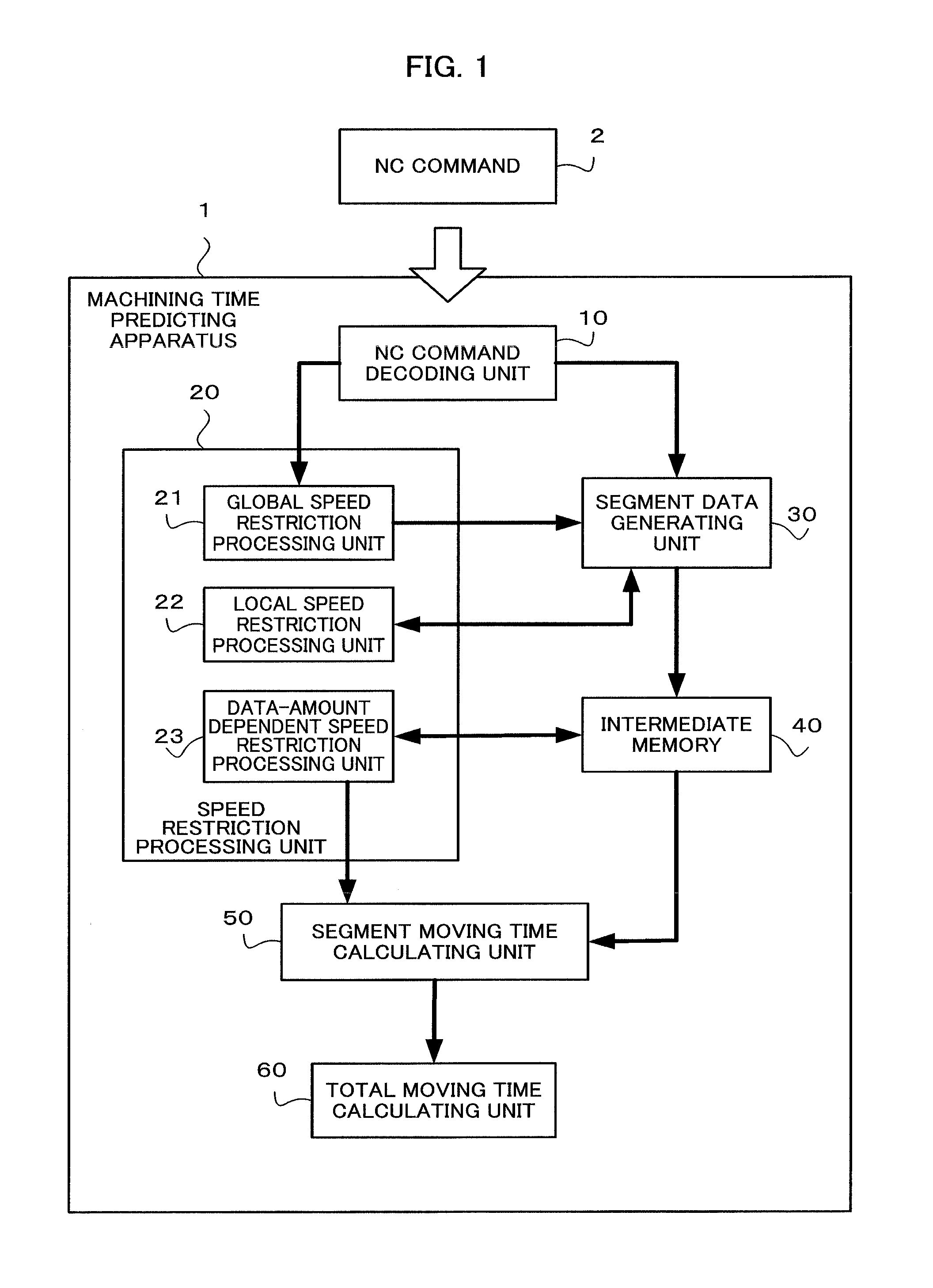
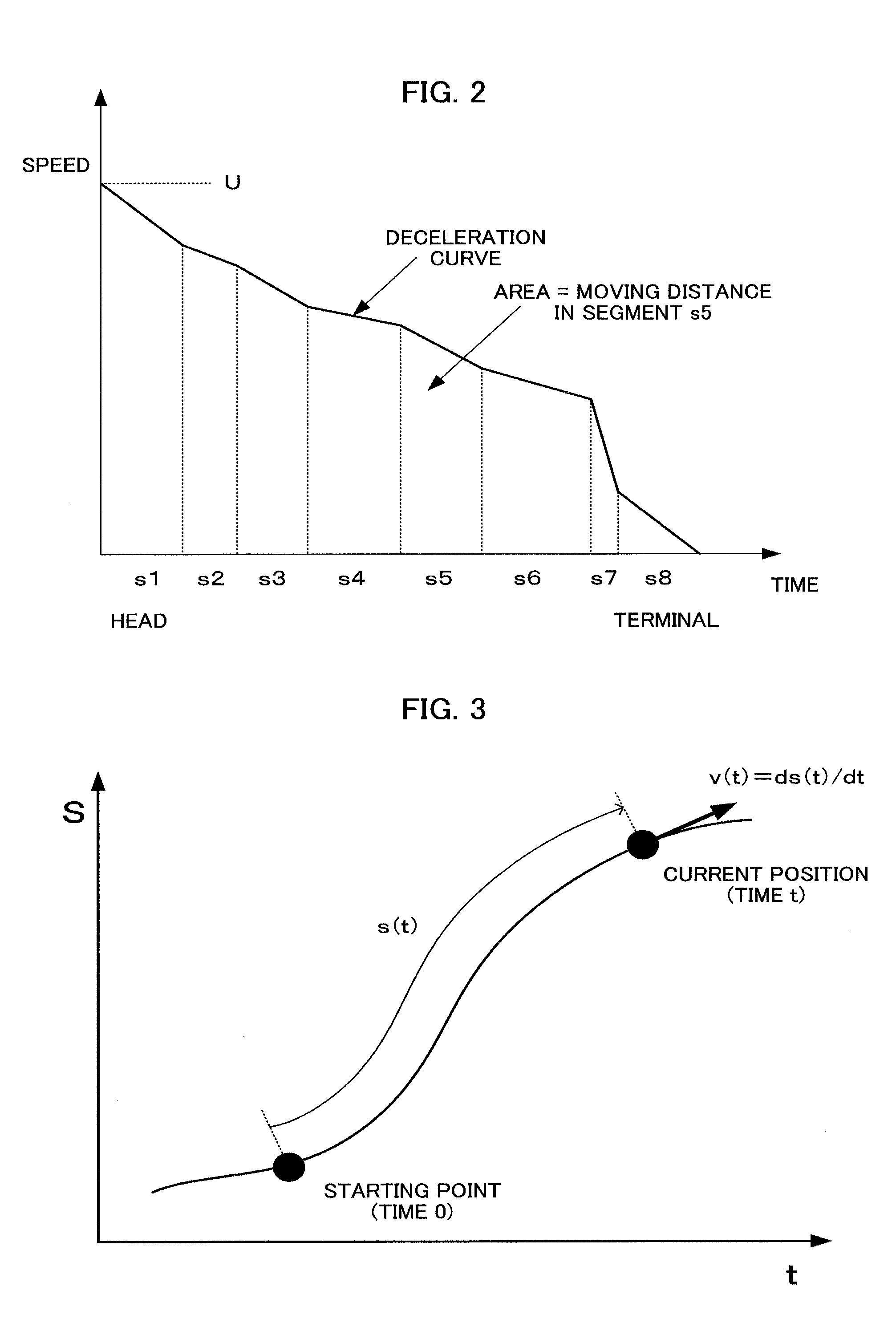
[0027]In the present invention, a tool path is divided into a plurality of segments. A speed curve indicating a change of a speed in a tangential direction is obtained from a starting point to a terminal of each segment. A time taken for the tool to move on the segment is calculated, supposing that the tool moves in accordance with the obtained speed curve. The time taken for the tool to move on the whole tool path can be given as a total of the moving times of the respective segments.

[0028]The speed curve is obtained by taking into consideration a restriction for the speed determined based upon a speed difference, acceleration difference, and a jerk difference between the adjacent segments, the curvature of the tool path, and the number of the segment data used for the calculation of the speed. Accordingly, the precision of the calculated processing time can be enhanced.

[0029]According to the present invention, the movement of the tool is not divided into an operation for each axis...


PUM


Abstract

A machining time predicting apparatus of a numerically controlled machine tool divides a tool path into a plurality of segments, obtains a speed in a tangential direction of each of the divided segments, calculates a time taken for the tool to move on each segment, and obtains the total of the calculated times taken for the tool to move on each segment as a tool moving time, in order to calculate a time (tool moving time) taken for the tool to move on the designated tool path according to an NC command.

Description

BACKGROUND OF THE INVENTION[0001]1. Field of the Invention[0002]The present invention relates to a machining time predicting apparatus of a numerically controlled machine tool, the apparatus calculating a time taken for a tool to move on a designated path according to a NC (numerical control) command.[0003]2. Description of the Related Art[0004]To predict beforehand a processing time by a numerically controlled machine tool is important for efficiently operate the machine tool. In order to predict the processing time, a user has to know a moving speed of a tool. A method described below has been known as a method of predicting an actual moving speed of a tool.[0005]Japanese Patent Application Laid-Open (JP-A) No. 2007-25945 describes a technique described below. Specifically, in this technique, a database of a speed control parameter, which is set according to at least either one of a type of a processing machine and a machining mode, is made. NC data (NC command) having a program o...

Claims


Application Information

Patent Timeline
Patent Type & Authority Applications(United States)
IPC IPC(8): G05B19/402
CPCG05B19/41865G05B2219/31407G05B2219/31429G05B2219/36219G05B2219/37336Y02P90/20Y02P90/265Y02P90/02
Inventor MIZUNO, TOHRUCHIBA, TAKUJI
Owner FANUC LTD
Why Eureka
Try Eureka