Breast pump system with actuator

a technology of actuators and breast pumps, applied in the field of breast pumps, can solve the problems of unexpected shutdown and uncontrollable shutdown of electric systems of breast pumps, and achieve the effect of improving system stability and high vacuum

Active Publication Date: 2017-11-14
KONINKLJIJKE PHILIPS NV
View PDF14 Cites 20 Cited by
  • Summary
  • Abstract
  • Description
  • Claims
  • Application Information

AI Technical Summary

Benefits of technology

[0007]The above approach has the advantage of improving the reliability of an electrical breast pump system. Furthermore, an uncontrolled shutdown of the breast pump system due to failure of the actuator may be prevented.
[0019]The power supply may be arranged to supply the electrical power to the actuator using pulse width modulation PWM, and the power supply control module may be arranged to determine the PWM duty cycle based on the detected input voltage and the predetermined voltage level. PWM control can allow a high battery input voltage to be reduced to the required output voltage by varying the PWM duty cycle accordingly. This allows the use of batteries with high input voltages relative to the required output voltage, increasing the useful operating time that can be provided by an individual battery before the input voltage falls below the minimum required level.

Problems solved by technology

It is known that electrical systems in breast pumps could shutdown unexpected and uncontrolled.

Method used


Image

  • Breast pump system with actuator
  • Breast pump system with actuator
  • Breast pump system with actuator

Examples


Embodiment Construction

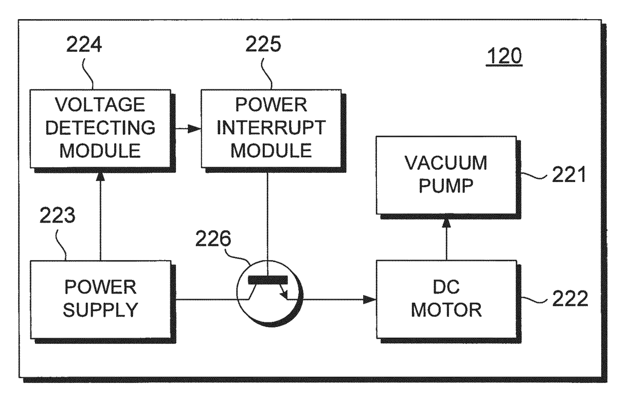
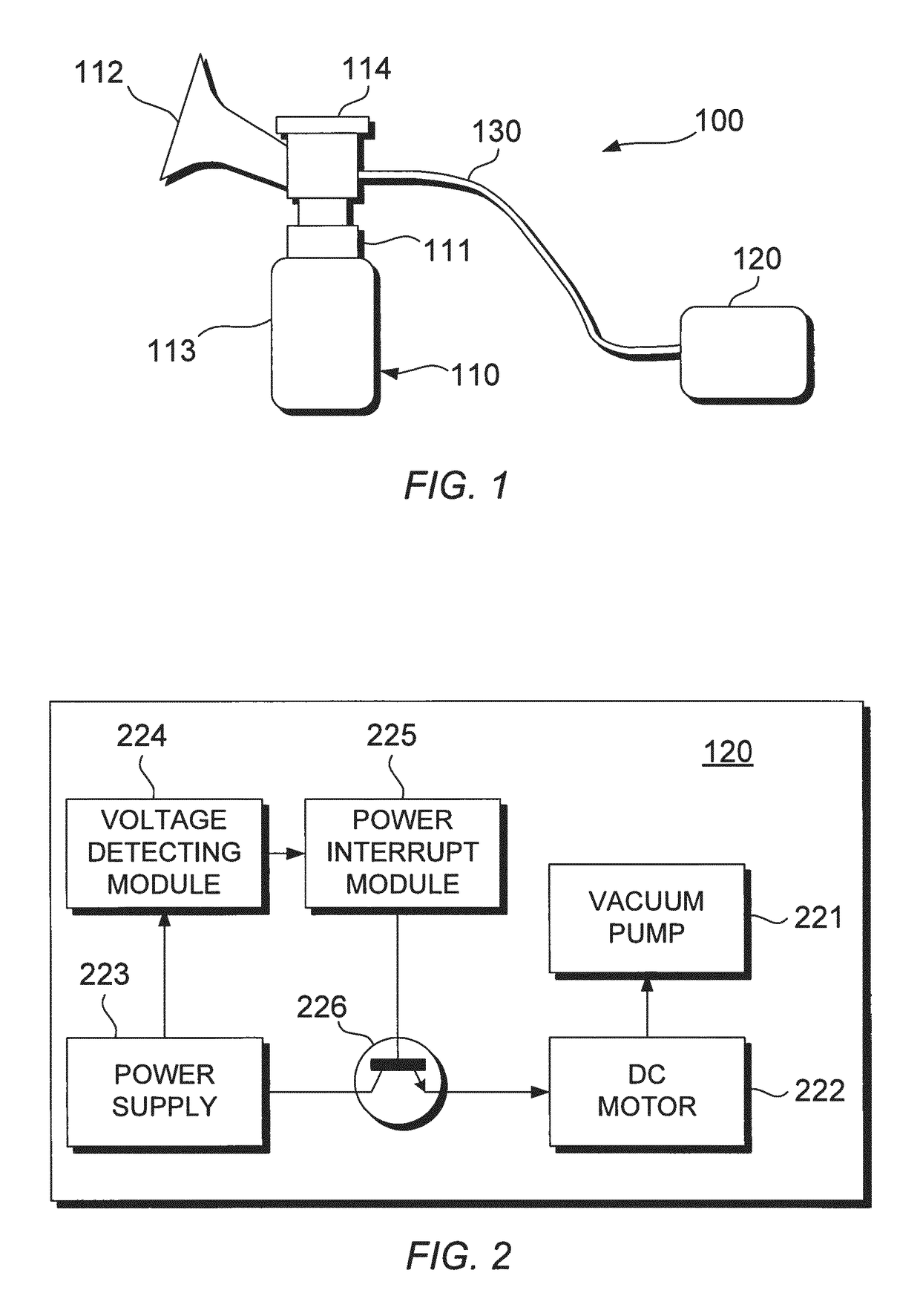
[0036]Referring now to FIGS. 1 and 2, a breast pump system is illustrated according to an embodiment of the present invention. As shown in FIG. 1, the breast pump system 100 includes a breast pump 110, also known as an expression unit, and an operating unit 120 connected by a tube 130 to the breast pump 110. The tube 130 provides a fluid communication between the breast pump 110 and the operating unit 120. The tube 130 may also be used to provide an electrical connection between the breast pump 110 and the operating unit 120. For example, the tube may supply an operating signal or electrical power between the breast pump and the operating unit. Although the operating unit 130 is spaced from the breast pump 110 in the present arrangement, it will be understood that the operating unit may be integrally formed with the breast pump 110.

[0037]The breast pump 110 has a main body 111, funnel 112, collection vessel 113 and a diaphragm 114 coupled to the vacuum line 130. The collection vesse...


PUM


Abstract

The present application relates to a breast pump system comprising a vacuum pump, an actuator for driving the vacuum pump, and a power supply for supplying electrical power to a plurality of components including the actuator, and also to a method for use in such as system. An output voltage of the power supply is detected, and in response to the detected output voltage being less than a first threshold voltage, the supply of electrical power to a predetermined one of the plurality of components is suspended. Then, if the detected output voltage recovers to a level above a second threshold value, the supply of electrical power is resumed.

Description

CROSS-REFERENCE TO PRIOR APPLICATIONS[0001]This application is the U.S. National Phase application under 35 U.S.C. §371 of International Application No. PCT / EP2013 / 061669, filed on Jun. 6, 2013 which claims the benefit of U.S. Provisional Patent Application No. 61 / 704702, filed on Sep. 24, 2012, and EP application No. 12185580.3, filed on Sep. 24, 2012. These applications are hereby incorporated by reference herein.FIELD OF THE INVENTION[0002]The present invention relates to breast pumps. More particularly, the present invention relates to interrupting the supply of electrical power to a predetermined one of a plurality of components in a breast pump system.BACKGROUND OF THE INVENTION[0003]Breast pumps are used by mothers to express breast milk at a convenient time, to be stored for later consumption by their child. The breast pump operates by generating a vacuum to mimic the feeding action of the child. Conventional breast pumps can be categorised as mechanical, in which a user man...

Claims


Application Information

Patent Timeline
Patent Type & Authority Patents(United States)
IPC IPC(8): A61M1/06
CPCA61M1/062A61M1/06A61M2205/8212A61M2205/33A61M2205/70A61M2205/18
Inventor AALDERS, ARNOLDBEULEN, GODEFRIDUS GERTRUDA WILLEMEL BARAKAT, HASSANDEN BEKKER, THEODORUS JOHANNES ADRIANUS MARIA
Owner KONINKLJIJKE PHILIPS NV
Why Eureka
Try Eureka