Vehicle-use dual voltage type power supply apparatus

Inactive Publication Date: 2008-09-04
DENSO CORP
View PDF2 Cites 20 Cited by
  • Summary
  • Abstract
  • Description
  • Claims
  • Application Information

AI Technical Summary

Benefits of technology

[0023]According to the present invention, it is possible to provide a vehicle-use dual voltage type power supply apparatus that can show a

Problems solved by technology

However, the results of improving fuel consumption have fallen short of the expectations.
This seems due to that the electricity cost reduction

Method used


Image

  • Vehicle-use dual voltage type power supply apparatus
  • Vehicle-use dual voltage type power supply apparatus
  • Vehicle-use dual voltage type power supply apparatus

Examples


Embodiment Construction

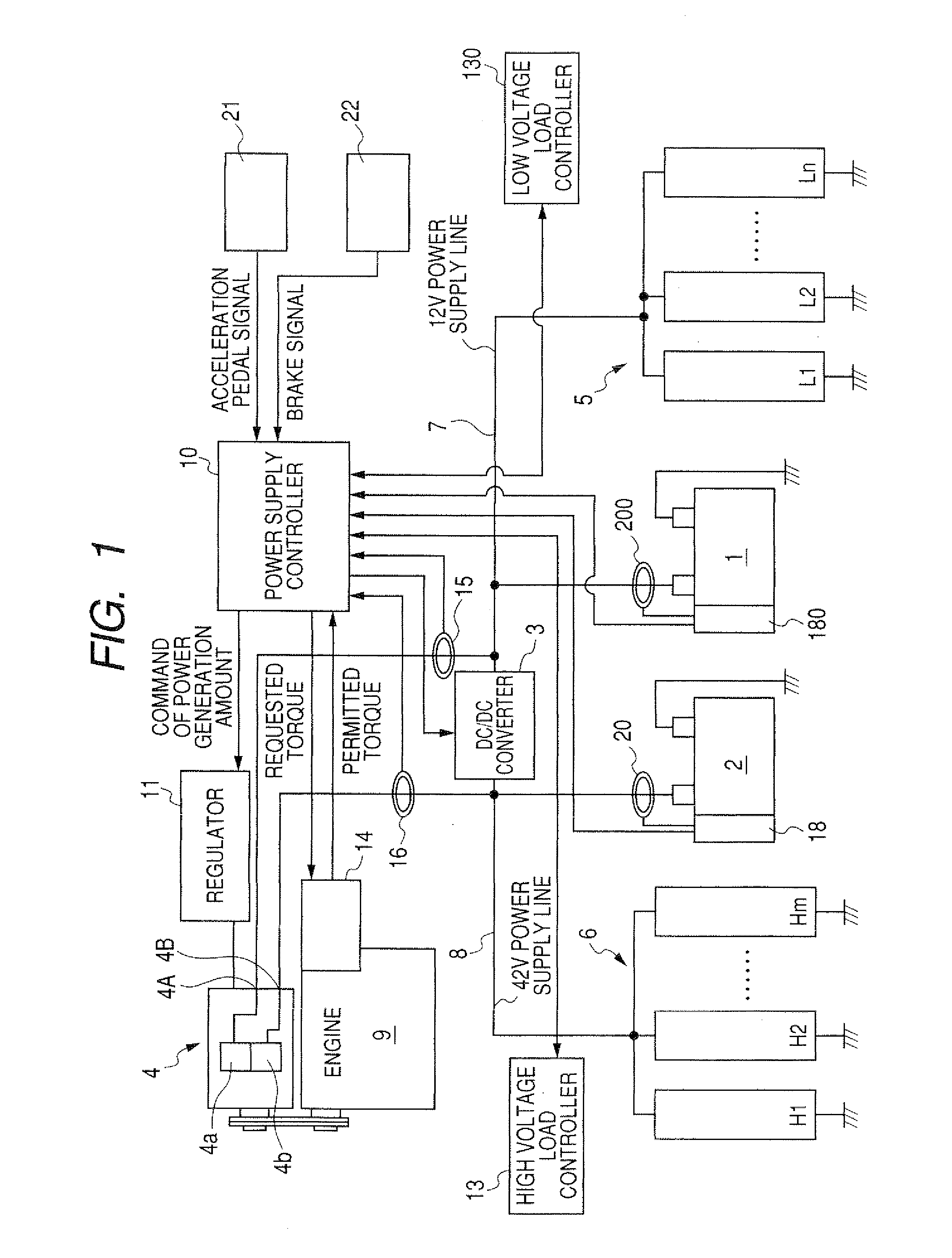
[0036]FIG. 1 is a diagram showing a circuit structure of a vehicle-use dual voltage type power supply apparatus according to an embodiment of the invention.

[0037]First, explanation is made as to power supply systems of the dual voltage type power supply apparatus.

[0038]In FIG. 1, the reference numeral 1 denotes a first battery whose rated voltage is 14V, 2 denotes a second battery whose rated voltage is 42V, 3 denotes a DC power transmission device performing electric power transmission between these batteries 1 and 2, 4 denotes a dual-voltage type generator outputting two different voltages as high and low power supply voltages, 5 denotes a low voltage load group including low voltage loads operating on the low power supply voltage, 6 denotes a high voltage load group including high voltage loads operating on the high power supply voltage, 7 denotes a low voltage power supply line, and 8 denotes a high voltage power supply line.

[0039]The dual voltage type generator 4 is constituted...


PUM


Abstract

The vehicle-use dual voltage type power supply apparatus including a high voltage power supply system and a low voltage power supply system has a configuration that the target power generation cost is calculated individually for each of the two power supply systems in accordance with SOC as a variable of its own battery, so that the electricity cost reduction type power generation control can be performed individually for each of the two power supply systems.

Description

CROSS-REFERENCE TO RELATED APPLICATION[0001]This application is related to Japanese Patent Application No. 2006-339925 filed on Dec. 18, 2006, the contents of which are hereby incorporated by reference.BACKGROUND OF THE INVENTION[0002]1. Field of the Invention[0003]The present invention relates to a vehicle-use power supply apparatus including a plurality of power supply systems each having a generator and a battery, and each operating to supply different voltages.[0004]2. Description of Related Art[0005]The importance of improving vehicle fuel consumption is increasing more and more in recent years because of the soaring fuel price. In order to improve vehicle fuel consumption, the applicant of this invention has proposed the electricity cost reduction type power generation control in which a target power generation cost CP is calculated as a function of an SOC (State Of Charge) of a battery, and electric power generation by a generator is boosted when a power generation cost Cg is...

Claims


Application Information

Patent Timeline
IPC IPC(8): B60L11/02B60L50/10B60L50/15B60L50/16
CPCH02J7/1423Y02T10/84
Inventor AOYAMA, KIYOSHITAMURA, HIROSHIKATO, AKIRA
Owner DENSO CORP
Why Eureka
Try Eureka