Method of diagnosing abnormality of reduction gear and apparatus for carry out the method

a technology of reduction gear and abnormality, which is applied in the direction of instruments, nuclear engineering, nuclear elements, etc., can solve the problems of affecting production efficiency, affecting a long period of time for the repair of the reduction gear and the normality of the robot, so as to improve production efficiency, accurate diagnosis, and increase the availability of machines

Inactive Publication Date: 2008-09-04
FANUC LTD
View PDF13 Cites 28 Cited by
  • Summary
  • Abstract
  • Description
  • Claims
  • Application Information

AI Technical Summary

Benefits of technology

[0010]It is an object of the present invention to provide a method of diagnosing abnormality of a reduction gear and an apparatus for carry out the method, in which the reduction gear is cap

Problems solved by technology

While this method has been very effective because of its ability to non-destructively detect an abnormality of a robot or a machine tool, it also has various disadvantages in that the abnormality can only be detected after the anomaly has occurred.
For example, it takes a long period of time to repair a reduction gear and restore a normality of a robot.
An abnormality of a joint is caused by wear, degradation of a bearing, a gear, a reduction gear, or the like.
With the conventional method as described above, there is a problem that, since various noises are contained in the signal detected by the sensor, it is not possible to directly extract only such a signal, which is effective for the diagnosis of the joint and to accurately predict an occurrence of an abnormality from the detected signal.
In other words, in the conventional method in which it is estimated that a fault may s

Method used


Image

  • Method of diagnosing abnormality of reduction gear and apparatus for carry out the method
  • Method of diagnosing abnormality of reduction gear and apparatus for carry out the method
  • Method of diagnosing abnormality of reduction gear and apparatus for carry out the method

Examples


Embodiment Construction

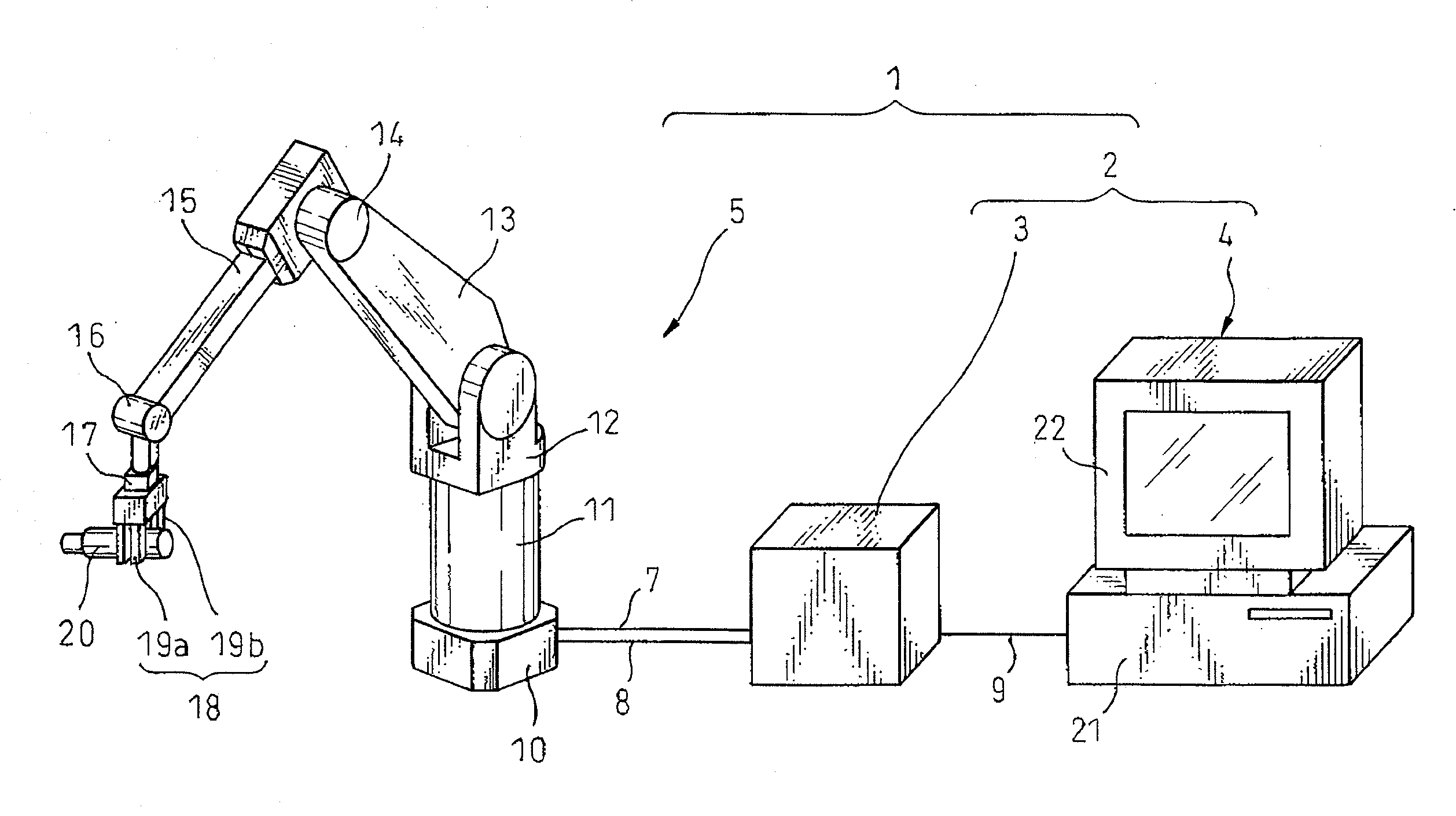
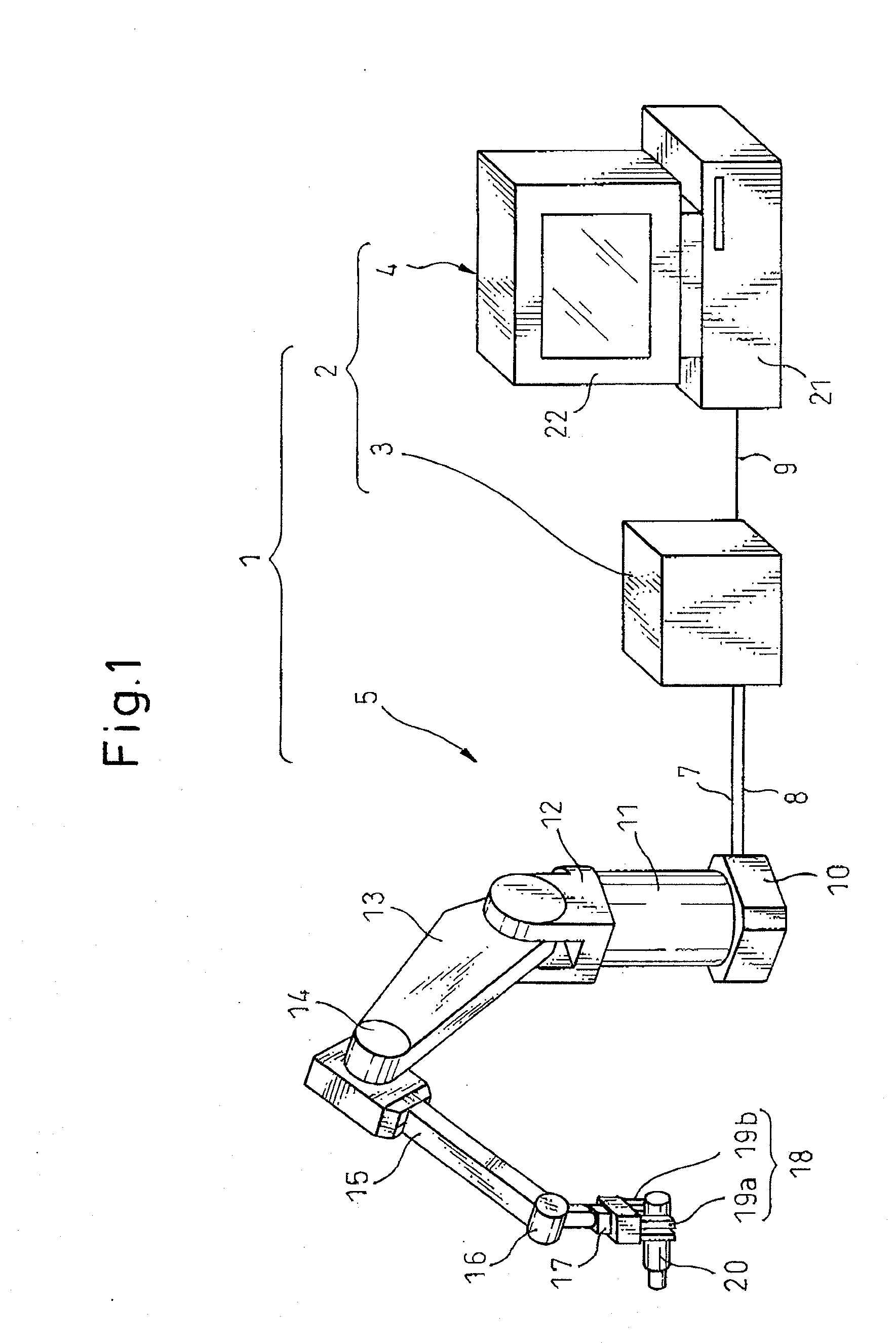
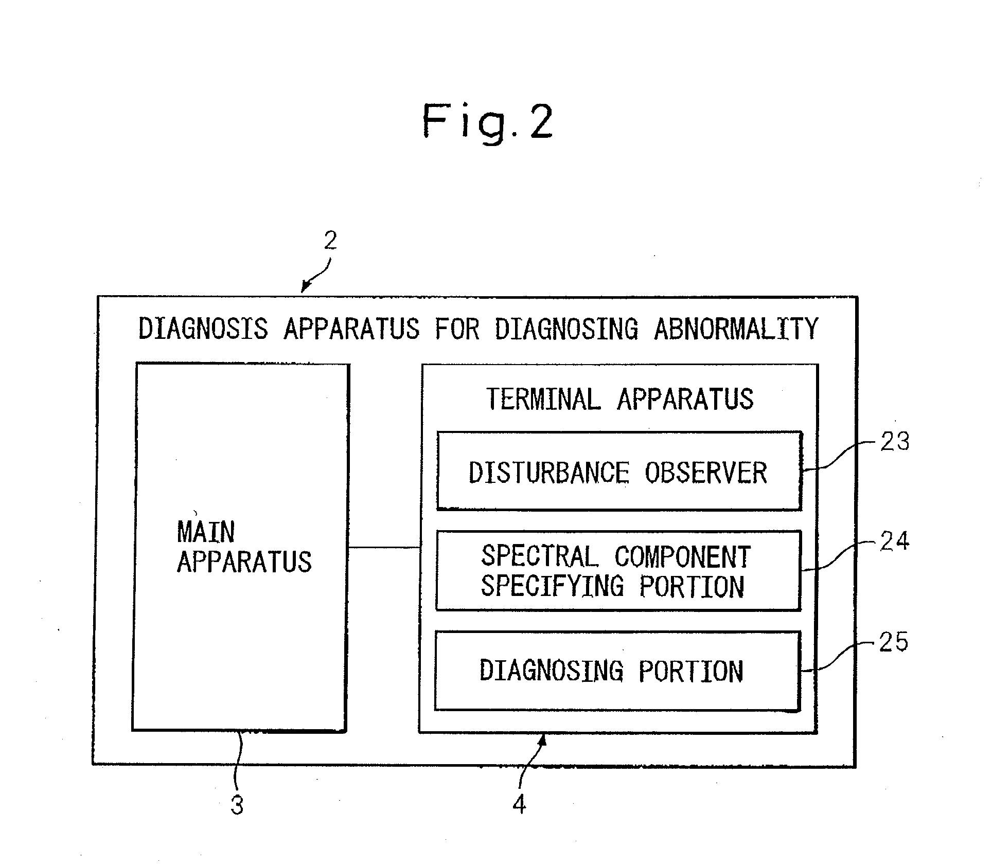
[0023]The present invention will be described in detail below with reference to the drawings showing specific examples of embodiments thereof. FIG. 1 is a view showing the system construction comprising an apparatus for carry out a method of diagnosing abnormality of a reduction gear according to an embodiment of the present invention. The apparatus 2 is a diagnosis apparatus that diagnoses an abnormality such as a failure of an input shaft as a fiction abnormality of an unshown reduction gear, and is composed of a main apparatus 3 for controlling a robot 5 and a terminal apparatus 4 for sending and receiving a signal to and from the main apparatus 3. A diagnosis system 1 is composed of the diagnosis apparatus 2 and the robot 5 comprising a reduction gear integrated with a motor as one unit. The robot 5 and the main apparatus 3 are electrically interconnected to each other via a power cable 7 and a signal line 8. The main apparatus 3 and the terminal apparatus 4 are electrically int...


PUM


Abstract

An apparatus for carry out a method of diagnosing abnormality of a reduction gear, the reduction gear including an intermediate shaft element disposed between an input shaft and an output shaft and rotating in proportion to a rotation of the input shaft to transmit the rotation to the output shaft, the apparatus has: a disturbance observer that obtains an estimated disturbance value regarding the reduction gear, based on a torque instruction and a velocity feedback-value acquired when a pair of driven members which rotate relative to each other with a motor as a driving source are in relative rotation at a constant velocity; a specific spectral component specifying portion for extracting a specific spectral component corresponding to a constant multiple of a rotational frequency of the intermediate shaft element from a frequency components of the estimated disturbance value obtained by frequency analysis; and a diagnosing portion, which compares an amplitude of the specific spectral component specified by the specific spectral component specifying portion with a threshold value, and diagnoses an abnormality in a case where the amplitude of the specific spectral component exceeds the threshold value, or a normality in a case where the amplitude of the specific spectral component is equal to or less than the threshold value.

Description

CROSS REFERENCE TO RELATED APPLICATIONFor Us[0001]The present application claims the priority of Japanese Patent Application No. 2006-204886, filed on Jul. 27, 2006, the disclosure of which is incorporated herein in its entirety by reference.BACKGROUND OF THE INVENTION[0002]1. Field of the Invention[0003]The present invention relates to a method of diagnosing abnormality of a reduction gear and an apparatus for carry out the method, in which the reduction gear has an intermediate shaft, for example, a crankshaft for eccentrically rotating an external gear in engagement with an internal gear, disposed between an input shaft and an output shaft for rotating in proportion to the rotation of the input shaft in order to transmit the rotation.[0004]2. Related Art[0005]As a method of diagnosing abnormality of a reduction gear, a method has been previously known in which an abnormality of a reduction gear is diagnosed based on information sent from a sensor mounted on the target part to be ...

Claims


Application Information

Patent Timeline
IPC IPC(8): G21C17/00
CPCG01M13/028G01M13/021
Inventor KATO, TETSUAKIKUROSHITA, TERUKI
Owner FANUC LTD
Why Eureka
Try Eureka