Water-flowing mechanism of wet type electrostatic precipitator

Inactive Publication Date: 2008-09-11
HITACHI PLANT TECH LTD
View PDF3 Cites 38 Cited by
  • Summary
  • Abstract
  • Description
  • Claims
  • Application Information

AI Technical Summary

Benefits of technology

[0021]According to the water-flowing mechanism in the wet type electrostatic precipitator of the present invention, the cylindrical member functions as a protective barrier that protects the droplets of the washing liquid, which are injected from the spray nozzle, from the airflow of the gas to be treated. Therefore, the droplets of the injected washing liquid is prevented from being caught in the airflow of the gas to be treated, like the spray nozzle system according to the conventional technique, whereby a stable water film can be formed on the entire surface of the dust-collecting plate by appropriately designing the attachment space of the spray nozzle. Particularly in the upflow type wet type electrostatic precipitator, the mechanism is effective since the upflow of the gas to be treated does not surely collides with the droplets of the washing liquid injected from the spray nozzle.
[0022]Compared to the water-flowing mechanism disclosed in JP-A-2002-224588 and JP-A-2001-190982, the wat

Problems solved by technology

However, the water-flowing mechanism in the wet type electrostatic precipitator described above has a problem such that water droplets of the washing liquid injected from the spray nozzles 108 are caught in the airflow of the gas to be treated 106, and therefore, a stable water film cannot be formed on the surface of each of the dust-collecting plates 104.
However, in the water-flowing mechanism disclosed in JP-A-2002-224588, when washing liquid is supplied to the empty water holding part 2 at the beginning of the operation, a plenty of washing liquid leaks from the partial gap between the opening part 4 and the dust-collecting plate 1, which means a plenty of washing liquid vigorously leaks.
Therefore, there arises a problem that even if the supplying flow-rate of the washing liquid from the water supplying tube 5 is increased more than the washing liquid leaking from th

Method used


Image

  • Water-flowing mechanism of wet type electrostatic precipitator
  • Water-flowing mechanism of wet type electrostatic precipitator
  • Water-flowing mechanism of wet type electrostatic precipitator

Examples


Example

[0039]FIG. 1 is a perspective view showing a first embodiment of a water-flowing mechanism of a wet type electrostatic precipitator according to the present invention, and FIG. 2 is a side view of the first embodiment. The first embodiment is characterized by including a dust-collecting plate 10, a water injecting pipe 20 that serves as a washing liquid supplying source that supplies the washing liquid to wet the dust-collecting plate, and a cylindrical member 16, of which a lower part opens according to the shape of upper end face of the dust-collecting plate 10 and into which the water injecting pipe 20 as a washing liquid supplying source, is inserted.

[0040]As shown in FIG. 2, plural dust-collecting plates 10 and discharge electrodes 12 are alternately arranged along a flow path of a flowing up gas to be treated 14 at equal intervals in a casing of the wet type electrostatic precipitator. High voltage is applied to the discharge electrodes 12, so that mist and dust in the gas to ...

Example

[0045]FIG. 3 is a side view showing a second embodiment of the water-flowing mechanism of a wet type electrostatic precipitator according to the present invention. In FIG. 3, the components having the numerals same as those in FIG. 2 have the function same as that in the first embodiment, therefore the explanation thereof is not repeated here. In the present embodiment, the lower opening 18 of a cylindrical member 16A is located at a position slightly higher than the upper end of the dust-collecting plate 10. The washing liquid flowing down to the lower opening 18 through the inner surface of the cylindrical member 16A reaches the dust-collecting plate 10 by inertial force based upon flow velocity energy, thereby forming a water film on the surface of the dust-collecting plate similar to the first embodiment.

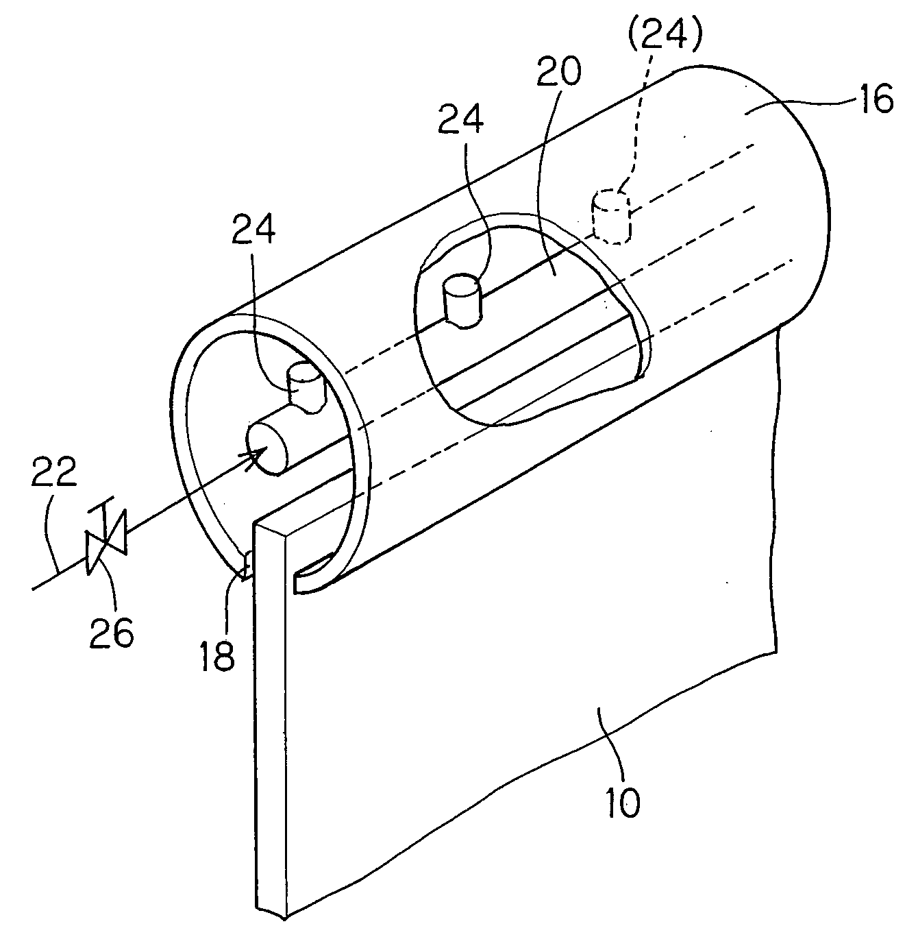
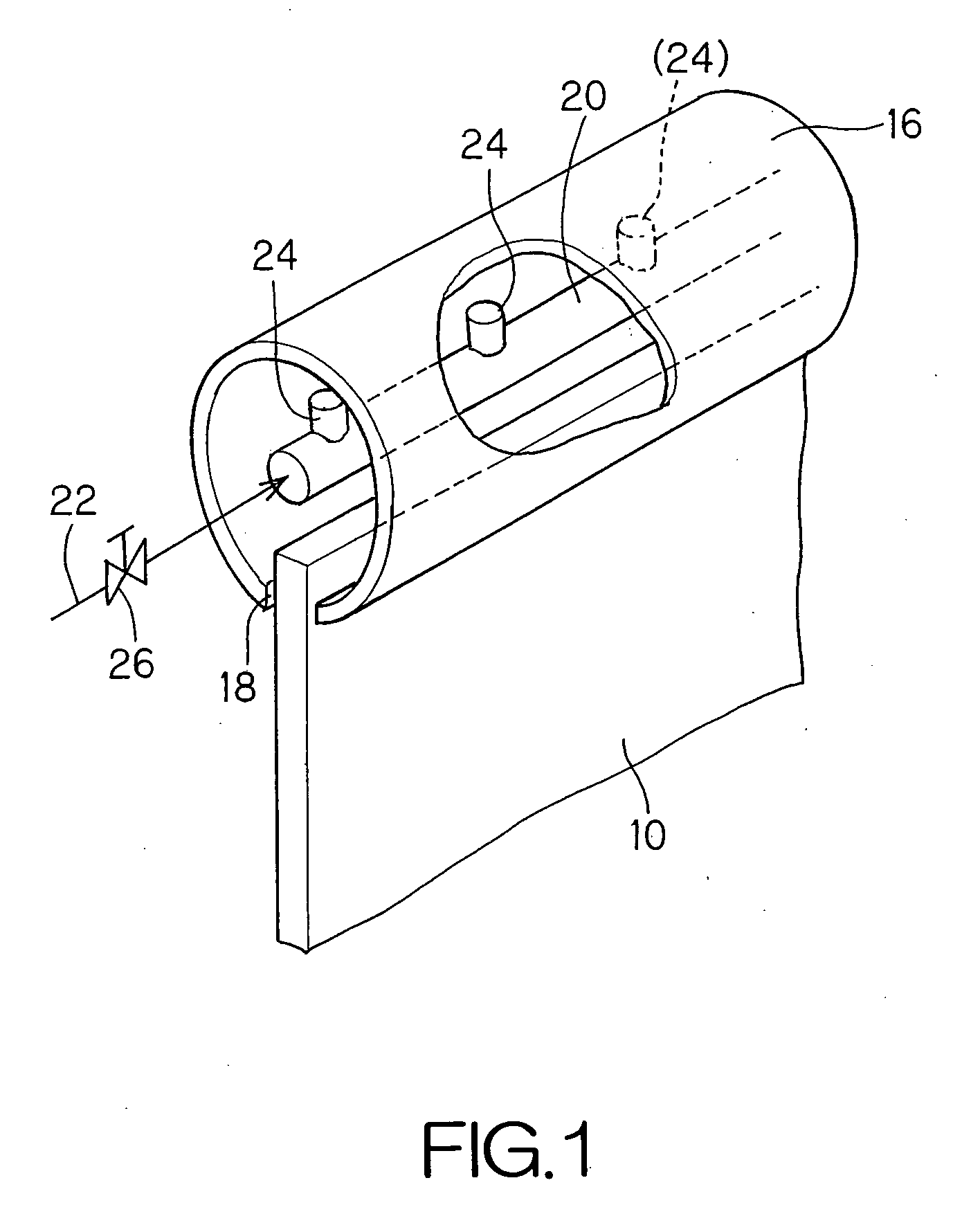
[0046]FIG. 4 is a side view showing a water-flowing mechanism of a wet type electrostatic precipitator of a third embodiment according to the present invention, and FIG. 5 is a ...

Example

[0047]The third embodiment is characterized by including a dust-collecting plate 10A, a spray nozzle 24 that supplies washing liquid to wet the dust-collecting plate 10A and serves as a washing liquid supplying source, and a cylindrical member 16, of which a lower part opens according to the shape of the upper end face of the dust-collecting plate 10 and into which the spray nozzle 24 as a washing liquid supplying source, is inserted, wherein the horizontal cross-section of the dust-collecting plate 10 is formed in a corrugated shape, and the lower opening 18 of the cylindrical member 16B is formed in a corrugated shape according to the dust-collecting plate 10A.

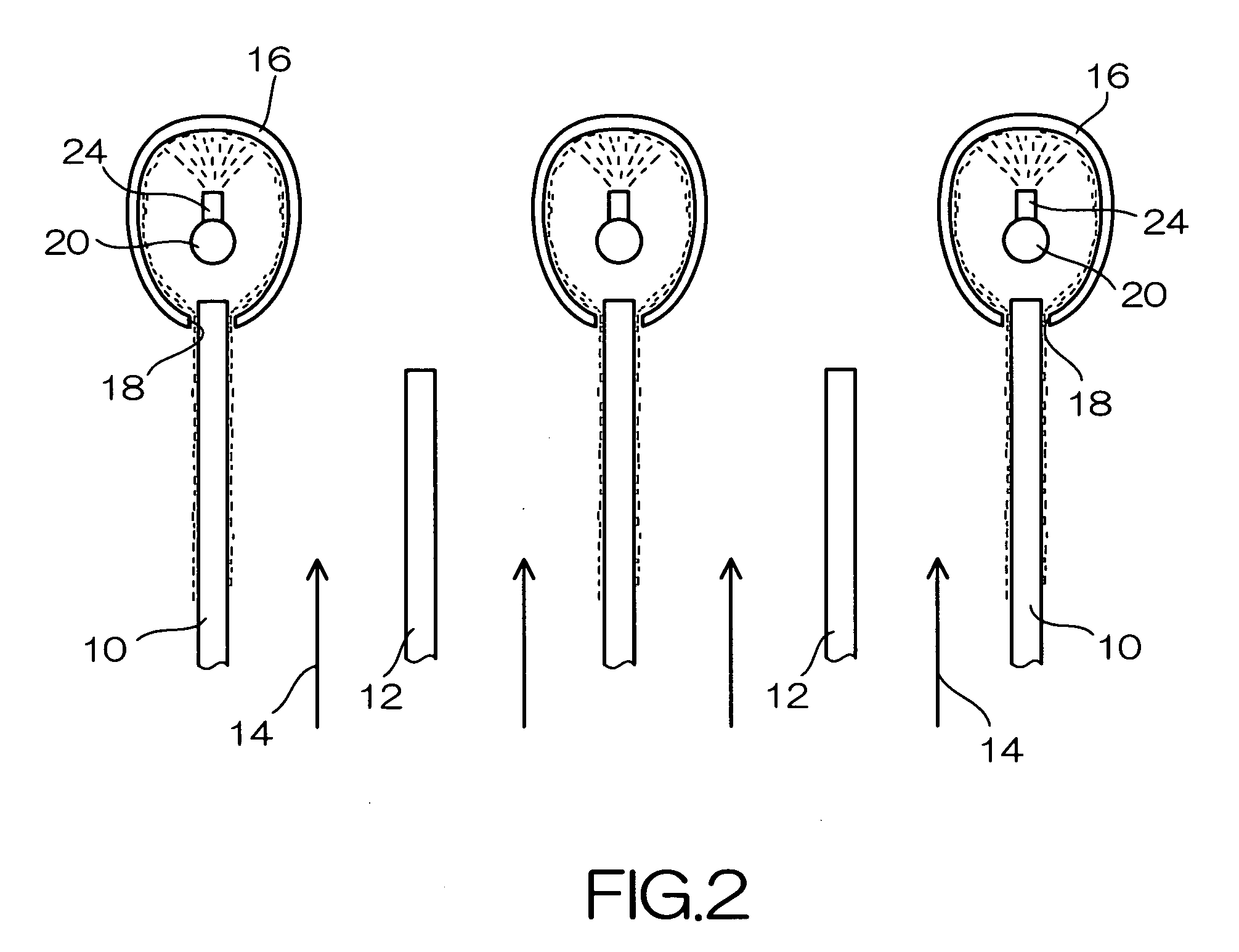
[0048]In FIGS. 4 and 5, the components having the numerals same as those in FIG. 2 have the functions similar to those in the first embodiment, therefore the explanation is not repeated here. The water-flowing mechanism according to the present embodiment may be applicable to the case in which the horizontal cross-section of...


PUM

PropertyMeasurementUnit
Flow rateaaaaaaaaaa
Shapeaaaaaaaaaa

Abstract

The present invention provides a water-flowing mechanism in a wet type electrostatic precipitator that can stably and quickly form a water film on a dust-collecting plate even at the beginning of the operation and that has an excellent adjusting function of a supplying flow-rate of washing liquid. The present invention includes a dust-collecting plate, a washing liquid supplying source to wet the dust-collecting plate, and a cylindrical member that is opened according to the shape of the upper end face of the dust-collecting plate and into which the washing liquid supplying source is inserted, wherein the horizontal cross-section of the dust-collecting plate is formed in a corrugated shape, and the lower opening of the cylindrical member is formed in a corrugated shape according to the dust-collecting plate.

Description

BACKGROUND[0001](a) Field of the Invention[0002]The present invention relates to a water-flowing mechanism of a wet type electrostatic precipitator, and more particularly to a water-flowing mechanism of a wet type electrostatic precipitator having plural dust-collecting plates along a flow path of gas to be treated.[0003](b) Description of the Related Art[0004]From exhaust gas from a boiler using heavy oil or coal as a fuel such as a thermal power plant, dust is removed by a dry type electrostatic precipitator, then, sulfur oxides are removed by a wet desulfurizer, and finally, mist or dust remaining in the exhaust gas is removed by a wet type electrostatic precipitator.[0005]FIG. 14 is a general view of a wet type electrostatic precipitator according to a conventional art. FIG. 14A is a perspective view, FIG. 14B is a front view seen from an inlet port 102, and FIG. 14C is a side view of FIG. 14B. A wet type electrostatic precipitator 100 shown in FIG. 14A has a casing 101 (a porti...

Claims


Application Information

Patent Timeline
IPC IPC(8): B03C3/78B03C3/00
CPCB03C3/08B03C3/53B03C3/16
Inventor MAEKAWA, SACHIOYANAGIDA, MITSUAKIKAWABATA, SHINICHIORITA, KEIGOMOCHIZUKI, YOSHIHIKO
Owner HITACHI PLANT TECH LTD
Why Eureka
Try Eureka