
Resist coating method and apparatus

a technology of resist coating and apparatus, which is applied in the direction of liquid surface applicators, coatings, instruments, etc., can solve the problems of increasing the dispersion regarding pre-wet effects among the resist coating apparatuses, the inability of pre-wet solvents to produce stably pre-wet effects, and the inability to sufficiently improve the uniformity regarding the thickness of resists, so as to reduce the dispersion of pre-wet effects, stabilize the thickness, and produ

Inactive Publication Date: 2008-09-11
ELPIDA MEMORY INC
View PDF2 Cites 3 Cited by
  • Summary
  • Abstract
  • Description
  • Claims
  • Application Information

AI Technical Summary

Benefits of technology

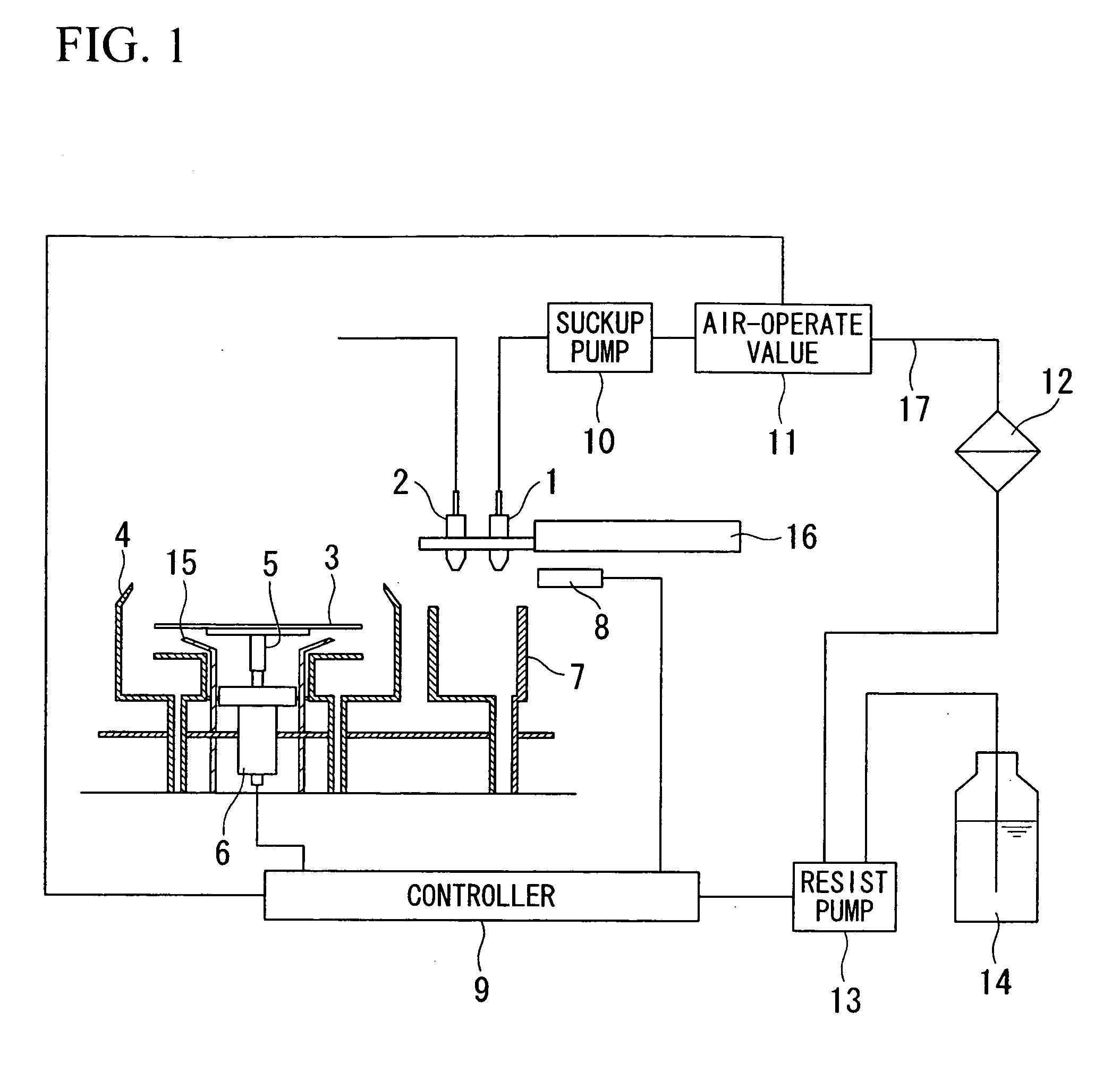
[0010]It is an object of the present invention to provide a resist coating method for applying a pre-wet solvent onto a semiconductor substrate before being applied with a resist, wherein it can stably produce a pre-wet effect, it can improve uniformity regarding the thickness of the resist, and it can reduce dispersion regarding pre-wet effects among a plurality of resist coating apparatuses.
[0011]It is another object of the present invention to provide a resist coating apparatus for applying a pre-wet solvent onto a semiconductor substrate before being applied with a resist, wherein it can stably produce a pre-wet effect, it can improve uniformity regarding the thickness of the resist, and it can reduce dispersion regarding pre-wet effects among a plurality of resist coating apparatuses.
[0012]Studies have been performed to solve the foregoing problems by paying attention to the relationship between dispersions of dry times for pre-wet solvents applied to semiconductor substrates (or wafers) and dispersions of pre-wet effects, wherein they are concluded in such a way that, by maintaining constant dry times for pre-wet solvents, it is possible to stably produce desired pre-wet effects and to adequately improve the uniformity regarding the thicknesses of resist films formed on semiconductor substrates.
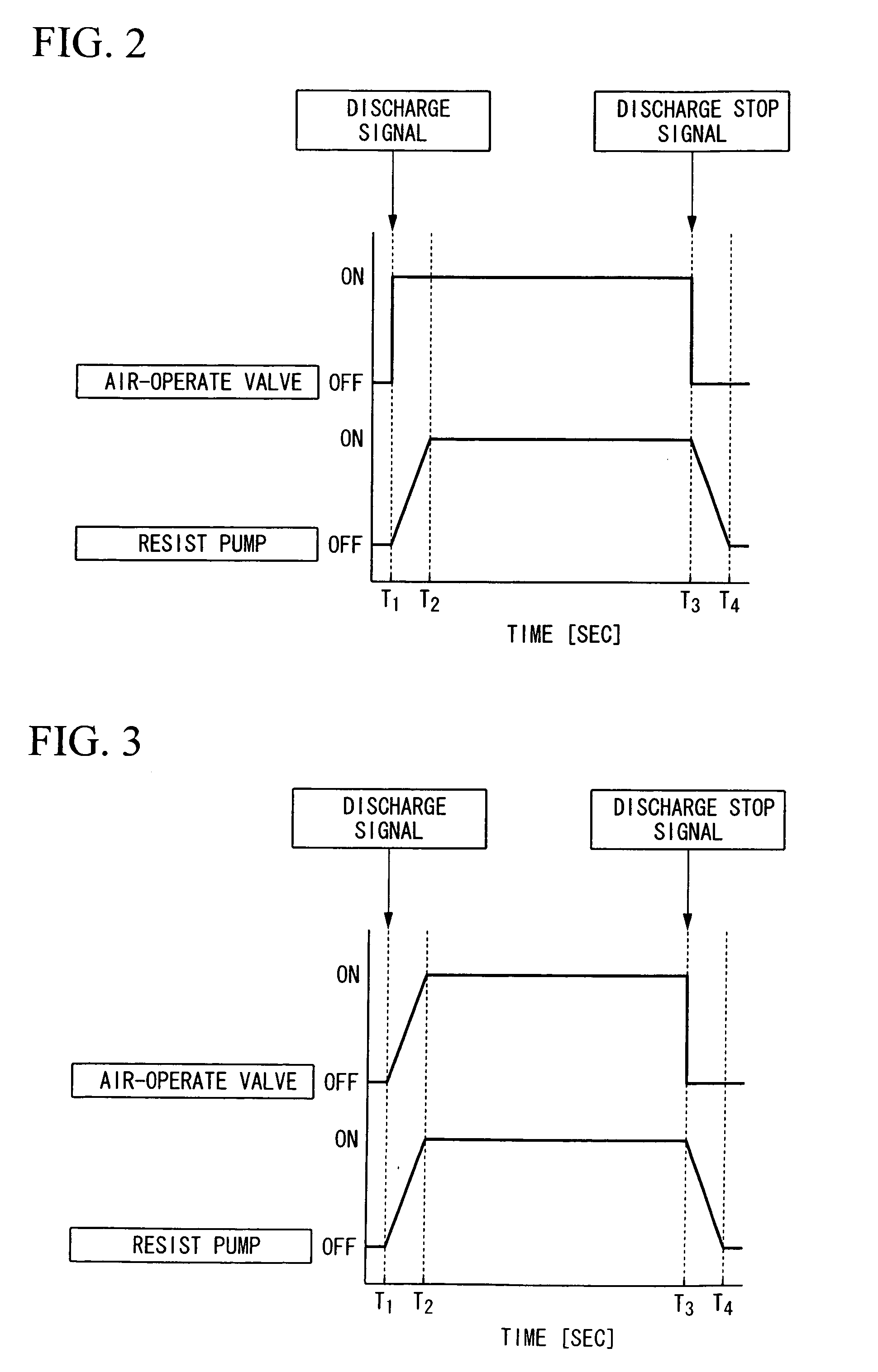
[0019]In the aforementioned resist coating method, the resist discharge signal is output at a timing that precedes the predetermined dry time being elapsed by the delay time; hence, it is possible to precisely match the timing for discharging the resist with the predetermined dry time being elapsed; thus, it is possible to normally maintain a constant dry time while avoiding negative influences due to the delay time.
[0021]Furthermore, the resist coating method is realized using a plurality of resist coating apparatuses, among which the dry time of the pre-wet solvent is normally maintained constant, thus reducing dispersion regarding the thickness of a resist film formed on the semiconductor substrate therebetween.
[0025]According to the present invention, the dry time of the pre-wet solvent is maintained constant irrespective of the delay time that is required for applying the resist onto the semiconductor substrate after completion of the dry process of the pre-wet solvent. Thus, it is possible to stably produce a pre-wet effect when the resist is spread over the semiconductor substrate, to stabilize the uniformity regarding the thickness of the resist film formed on the semiconductor substrate, and to reduce dispersion of pre-wet effects between resist coating apparatuses.

Problems solved by technology

However, the foregoing method regarding application of pre-wet solvents may not be capable of stably producing pre-wet effects when resists are spread over semiconductor substrates; hence, it is very difficult to sufficiently improve the uniformity regarding the thicknesses of resists.
In particular, a resist coating is realized using a plurality of resist coating apparatuses in parallel, which may increase dispersions regarding pre-wet effects among the resist coating apparatuses.

Method used


Image

  • Resist coating method and apparatus
  • Resist coating method and apparatus
  • Resist coating method and apparatus

Examples


working examples

3. WORKING EXAMPLES

(a) First Example

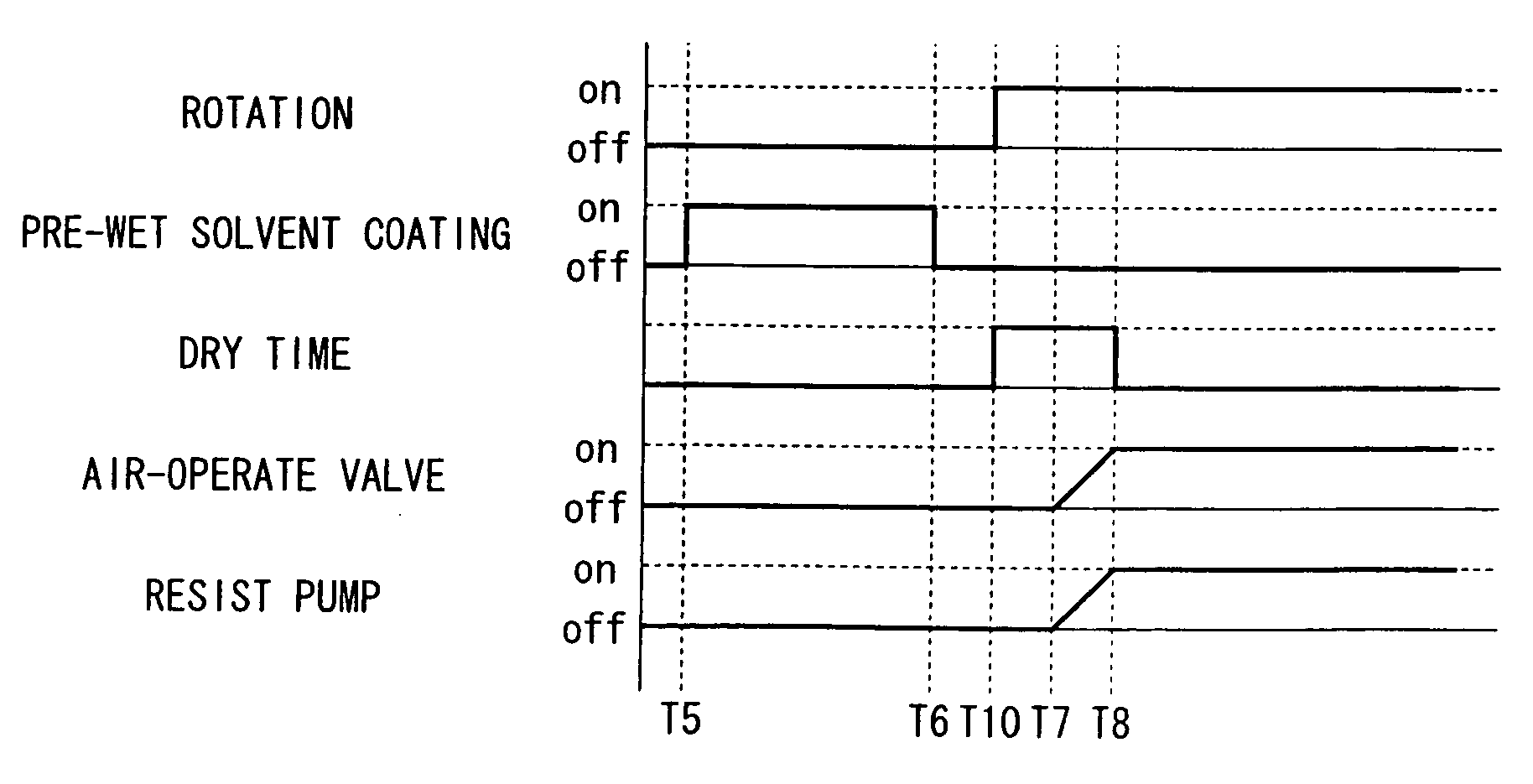
[0060]By use of the resist coating apparatus of FIG. 1, a resist is applied onto the semiconductor substrate 3 in accordance with the following method based on the time sequence shown in FIG. 7. The predetermined dry time adapted to the first example is set to 0.1 seconds. The predetermined dry time depends upon resist materials and coating thicknesses; hence, it can be experimentally determined in advance.

[0061]First, the discharge condition adjustment is performed so as to match the operation timing of the air-operate valve 11 with the operation timing of the resist pump 13.

[0062]Specifically, the operation timing of the air-operate valve 11 is deviated from the operation timing of the resist pump 13 by 0.06 seconds; hence, the operation timing of the air-operate valve 11 is delayed to match the operation timing of the resist pump 13.

[0063]After completion of the discharge condition adjustment, the dummy dispensation step is performed. In the du...

second example

(b) Second Example

[0069]A second example is dedicated to a method for normally maintaining a constant dry time by delaying the dry start timing by the delay time. The dummy dispensation step applied to the second example is substantially identical to that of the first example; hence, the description thereof will be omitted. Hence, the second example will be described with respect to the pre-wet step and its following step(s) with reference to the time sequence shown in FIG. 8. In the second example, the predetermined dry time is set to 0.1 seconds, and the delay time is set to 0.06 seconds.

[0070]After completion of the dummy dispensation step, the pre-wet step is performed. First, the semiconductor substrate 3 is mounted on the spin-chuck 5, then the nozzle arm 16 moves the solvent nozzle 2 to be positioned just above the semiconductor substrate 3. At time T5 shown in FIG. 8, the solvent nozzle 2 discharges a pre-wet solvent for 2.0 seconds without rotating the spin-motor 6. At time...

third example

(c) Third Example

[0074]The third example is basically identical to the first example except that another resist coating apparatus whose delay time is set to 0.02 seconds is used to apply a resist onto the semiconductor substrate 3.

[0075]Then, the pre-wet step is performed. In the pre-wet step, the semiconductor substrate 3 is mounted on the spin-chuck 5, wherein the nozzle arm 16 moves the solvent nozzle 2 to be positioned just above the center of the semiconductor substrate 3. Then, at time T5 shown in FIG. 7, the solvent nozzle 2 discharges a pre-wet solvent onto the semiconductor substrate 3 for 2.0 seconds without rotating the spin-motor 6. At time T6, the solvent nozzle 2 stops discharging the pre-wet solvent, and at the same time, the controller 9 controls the spin-motor 6 so as to rotate the semiconductor substrate 3 at a rotating speed of 1200 rpm, thus starting a coating-drying process (or a spin-drying process). In order to prepare for the next resist coating step, the noz...


PUM


Abstract

A resist coating method includes a dummy dispensation step for discharging a resist onto a semiconductor substrate in response to a dummy discharge signal, a pre-wet step for applying and then drying a pre-wet solvent on the semiconductor substrate, and a resist coating step for applying the resist onto the semiconductor substrate in response to a resist discharge signal. The resist discharge signal is output at a timing that precedes a predetermined dry time being elapsed by a delay time, which is calculated between the timing for outputting the dummy discharge signal and the timing for actually discharging the resist, thus normally maintaining the predetermined dry time constant. This makes it possible to stably produce pre-wet effects, to improve the uniformity regarding the thickness of a resist film formed on the semiconductor substrate, and to reduce dispersion regarding pre-wet effects between resist coating apparatuses.

Description

BACKGROUND OF THE INVENTION[0001]1. Field of the Invention[0002]The present invention relates to methods and apparatuses for coating semiconductor substrates with resists, wherein pre-wet solvents are applied to semiconductor substrates in advance and are then dried in prescribed periods of time.[0003]The present application claims priority on Japanese Patent Application No. 2007-59090, the content of which is incorporated herein by reference.[0004]2. Description of the Related Art[0005]Recently, resist coating apparatuses are arranged in parallel with each other so as to improve throughputs in resist coatings. It is required to uniform thicknesses of resists among resist coating apparatuses for applying resists to semiconductor substrates (or wafers). As a method for improving uniformity regarding thicknesses of resists, pre-wet solvents are applied to semiconductor substrates (or wafers) before the formation of resists in advance. This technology is disclosed in various documents ...

Claims


Application Information

Patent Timeline
Patent Type & Authority Applications(United States)
IPC IPC(8): B05C11/00H01L21/30
CPCG03F7/162
Inventor HOSHI, NOBUAKI
Owner ELPIDA MEMORY INC
Learn More