
Positive displacement rotary vane engine

Active Publication Date: 2008-09-11
HARTFIELD JR ROY J
View PDF42 Cites 16 Cited by
  • Summary
  • Abstract
  • Description
  • Claims
  • Application Information

AI Technical Summary

Benefits of technology

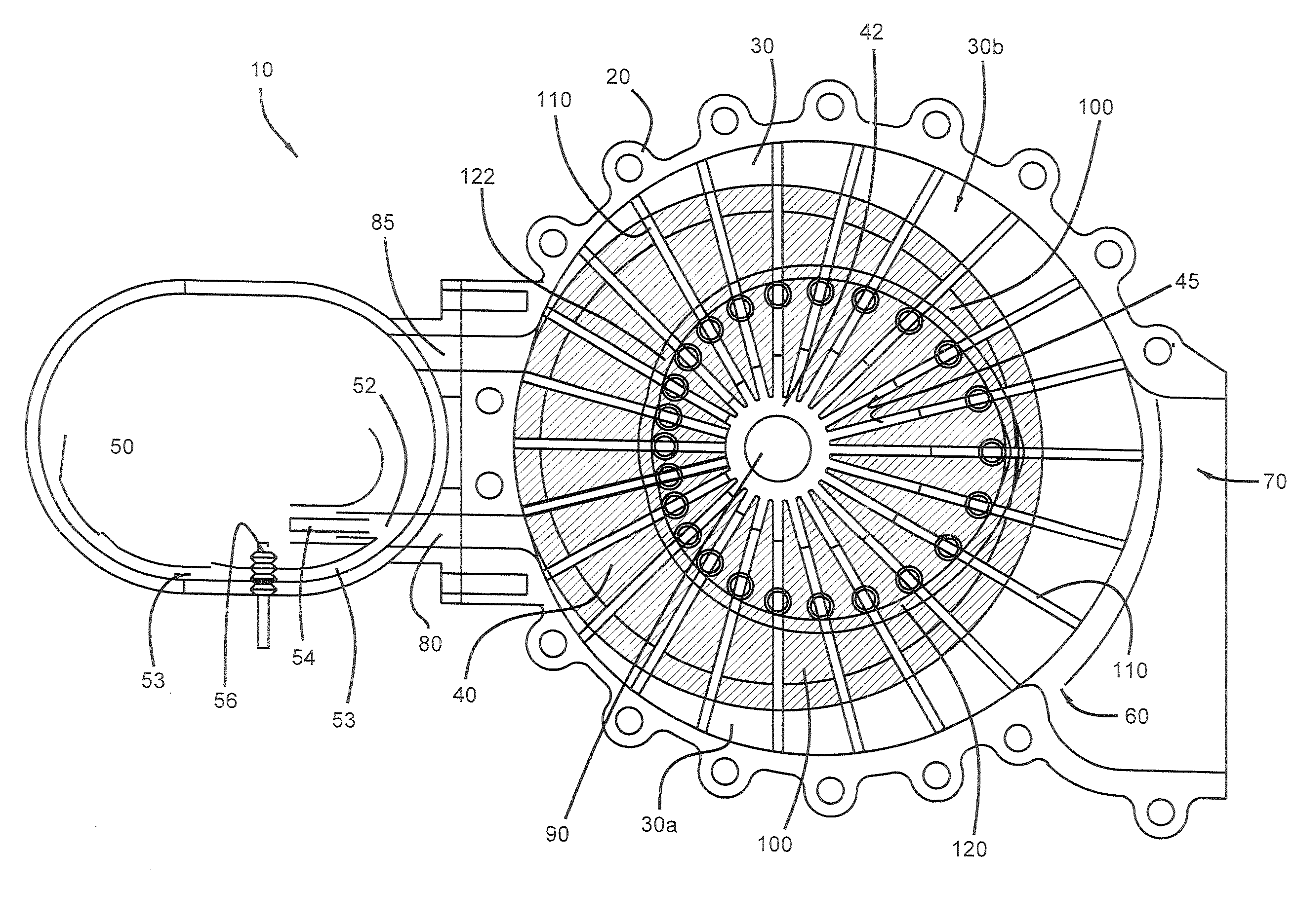
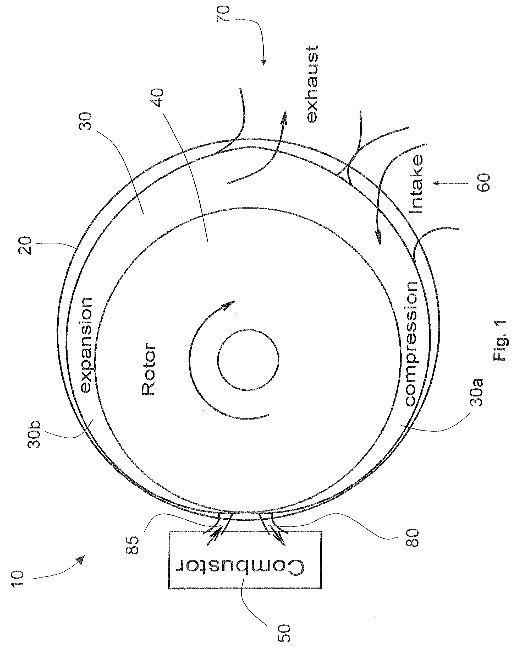
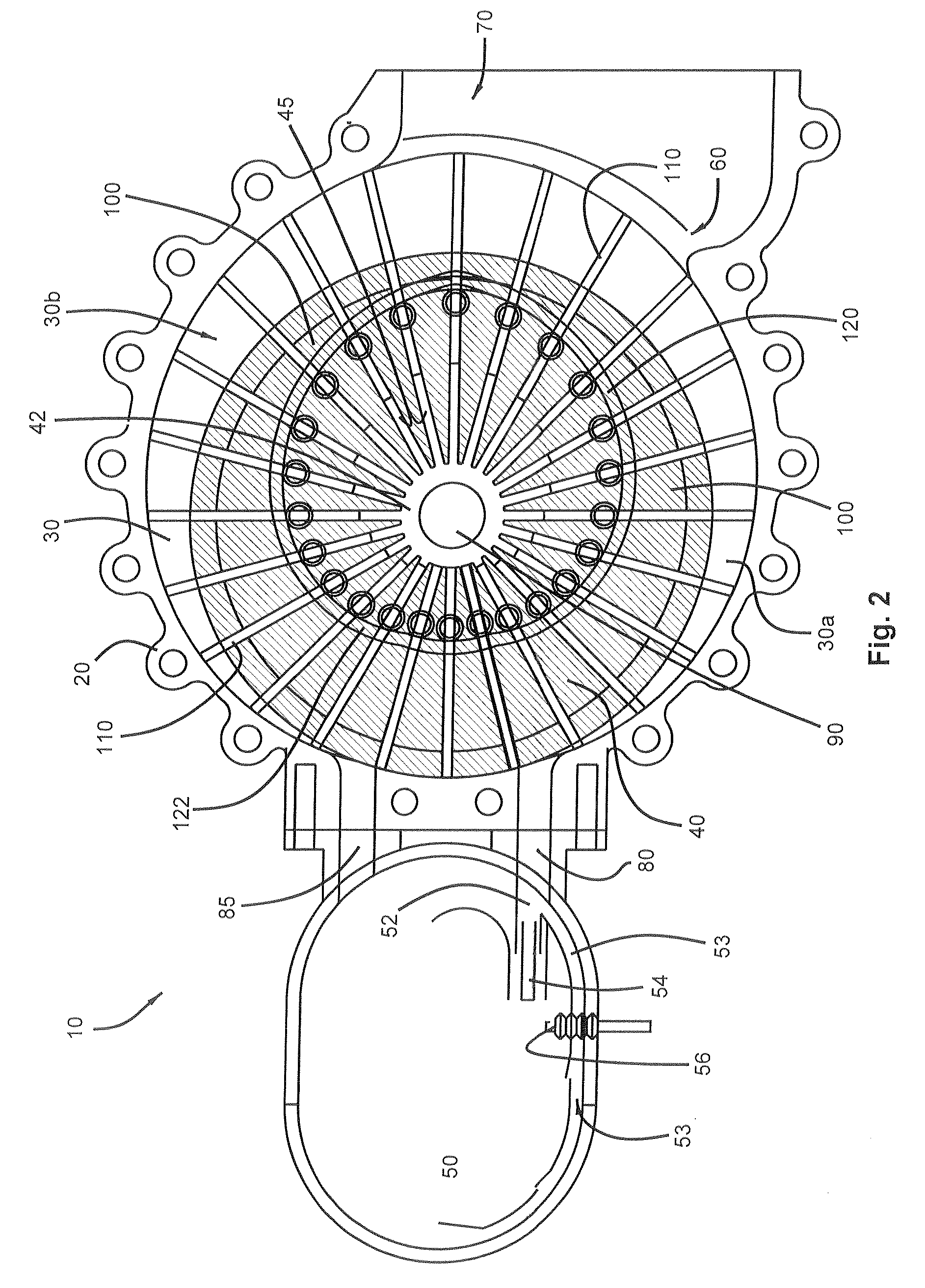
[0009]In example forms, the present invention is an engine that employs a positive displacement compression process, a variably fueled, continuous combustor (such as a combustor used in a gas turbine) and / or a heat exchanger, and a positive displacement, work-producing expander. This arrangement avoids the stochiometric mixture requirements with traditional spark-ignition engines based on the entire engine air mass flow rate and the inefficiencies of off-design compressor and turbine performance. Additionally, this arrangement is not compression ratio limited as spark-ignition engines are. Furthermore, the engine of the present invention significantly reduces engine emissions typical with the operation of diesel engines. Example embodiments of this engine as described herein are in the form of a sealable rotary vane device.

Problems solved by technology

One major disadvantage for spark-ignition engines is that they must operate in a mode in which the ratio of the fuel mass to the air mass in the engine at the combustion stage is near stoichiometric.
This effectively limits the compression ratio and, in turn, the efficiency of the engines.
The direct-injection spark-ignition and diesel engines are not as limited by this requirement but these two types of engines have significant emissions problems.
The disadvantage to running the Brayton cycle engines at partial power is explained by the fact that known axial flow compressor and turbine systems are inefficient at off-design operating points.
Another disadvantage of conventional piston engines is that the air is ported to the combustion chamber through valves, which limit the ability of the engine to breathe efficiently and introduce pumping losses even with wide open throttle settings.
This inherently limits the performance in the same way that piston engine performance is limited by combustion stoichiometry.
Additionally, the sealing of rotary vane devices for high temperature applications such as combustion engines has eluded inventors to date and excessive wear has hampered the success of known rotary vane devices of all types.
Without proper sealing, adequate compression and expansion cannot take place.

Method used


Image

  • Positive displacement rotary vane engine
  • Positive displacement rotary vane engine
  • Positive displacement rotary vane engine

Examples


Embodiment Construction

[0037]The present invention may be understood more readily by reference to the following detailed description of the invention taken in connection with the accompanying drawing figures, which form a part of this disclosure. It is to be understood that this invention is not limited to the specific devices, methods, conditions or parameters described and / or shown herein, and that the terminology used herein is for the purpose of describing particular embodiments by way of example only and is not intended to be limiting of the claimed invention. Also, as used in the specification including the appended claims, the singular forms “a,”“an,” and “the” include the plural, and reference to a particular numerical value includes at least that particular value, unless the context clearly dictates otherwise. Ranges may be expressed herein as from “about” or “approximately” one particular value and / or to “about” or “approximately” another particular value. When such a range is expressed, another...


PUM


Abstract

The present invention is an engine, which includes a positive displacement compression process, a variably fueled, continuous combustor and / or heat exchanger, and a positive displacement, work-producing expander. This arrangement avoids the traditional stochiometric mixture requirements utilized in spark-ignition based engines and the emission problems associated with diesel engines.

Description

CROSS-REFERENCE TO RELATED APPLICATION[0001]This application claims the benefit of U.S. Provisional Patent Application Ser. No. 60 / 892,913, filed Mar. 5, 2007, the entirety of which is hereby incorporated herein by reference for all purposes.TECHNICAL FIELD[0002]The present invention relates generally to engines. More particularly, this invention relates to positive displacement rotary vane engines.BACKGROUND OF THE INVENTION[0003]Premixed and direct-injection spark-ignition piston engines operating on the Otto cycle and direct injection engines operating on the diesel cycle represent the bulk of known engines used for motor vehicles. These engines are popular for a variety of reasons but, primarily, they are widely used because they offer reasonable efficiencies for a wide range of power settings. One major disadvantage for spark-ignition engines is that they must operate in a mode in which the ratio of the fuel mass to the air mass in the engine at the combustion stage is near sto...

Claims


Application Information

Patent Timeline
IPC IPC(8): F02B53/08
CPCF01C1/3441F01C21/0836F02B55/14Y02E10/46F01C1/04F04C2250/301F01C21/0881F04C27/002
Inventor HARTFIELD, ROY J.
Owner HARTFIELD JR ROY J
Learn More