Device for Limiting Current of Electric Appliance

a technology for limiting current and electric appliances, applied in the integration of power network operation systems, emergency protective arrangements for limiting excess voltage/current, and constant-current supply dc circuits, etc., can solve the problems of limited total output, limited total current amount, and limited operation of heaters, so as to improve safety and reliability of electric appliances.

Inactive Publication Date: 2008-09-11
LG ELECTRONICS INC
View PDF1 Cites 4 Cited by
  • Summary
  • Abstract
  • Description
  • Claims
  • Application Information

AI Technical Summary

Benefits of technology

[0014]According to the present invention, a current limiting device limits an allowable current according to power standards and limits a part of operations when a micom malfunctions. Consequently, since the cause of a fire is reduced, safety and reliability of electric appliance can be improved.

Problems solved by technology

In a case of electric appliance requiring a high output, its total output is limited according to standards and power safety.
That is, a total current amount is limited.
Further more, although the power cord is two-phase, the micom limits the operation of the heater for safety of an input power and electric appliance when a user operates the heater to exceed a total allowable current amount and also operational conditions are inputted to exceed a total allowable current amount.
The micom limits the operation of the heater in an aspect of software.
However, when only the micom limits a total output according to standards of a power, a current suddenly may exceed an allowable current in a case of micom malfunction.
Therefore, a circuit breaker is turned on or a fire due to a power cord overheating occurs.
That is, safety accident may occur.
Since there is no preparation for a micom malfunction, safety and reliability of a system deteriorate.

Method used


Image

  • Device for Limiting Current of Electric Appliance
  • Device for Limiting Current of Electric Appliance
  • Device for Limiting Current of Electric Appliance

Examples


Embodiment Construction

[0018]Reference will now be made in detail to the preferred embodiments of the present invention, examples of which are illustrated in the accompanying drawings.

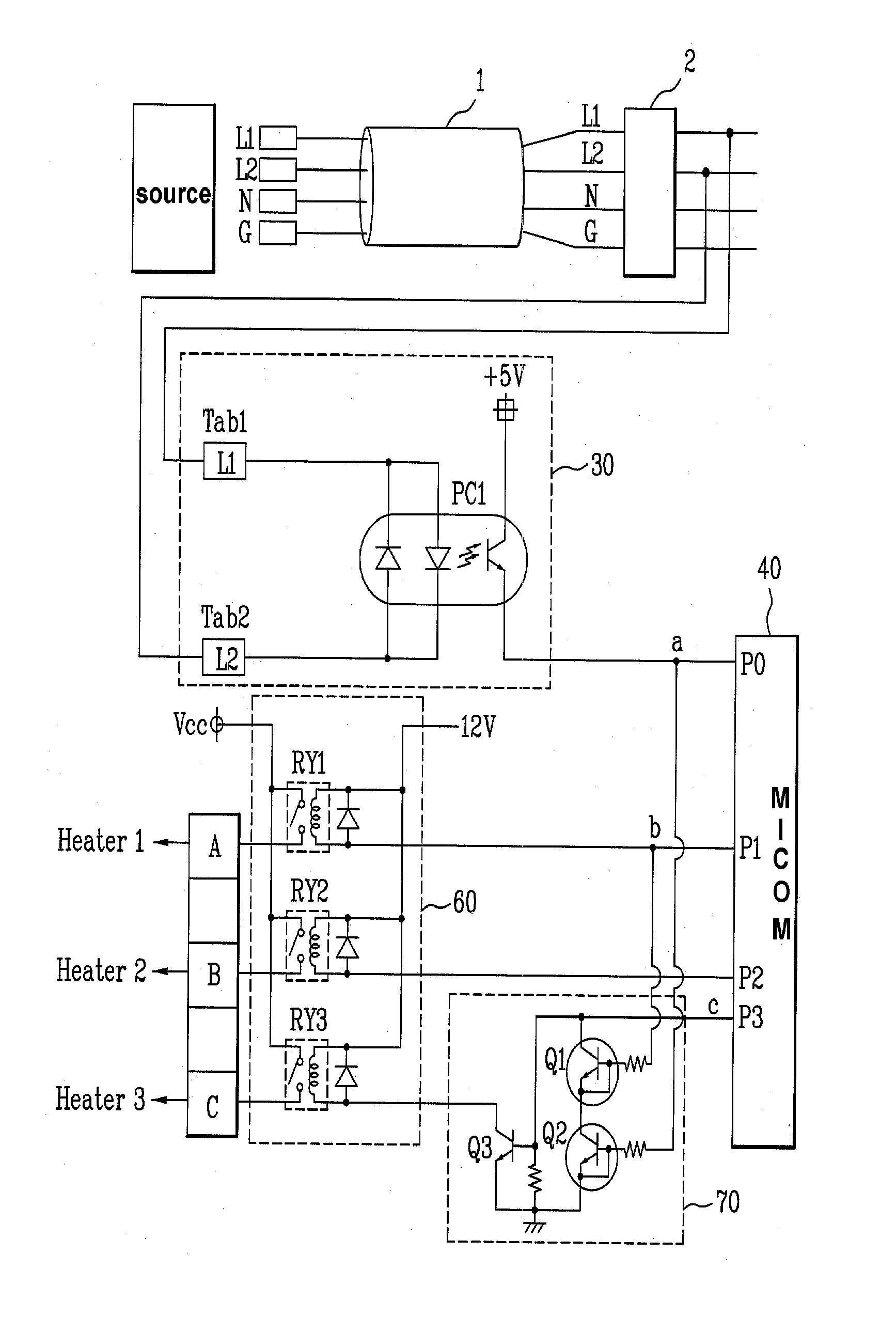
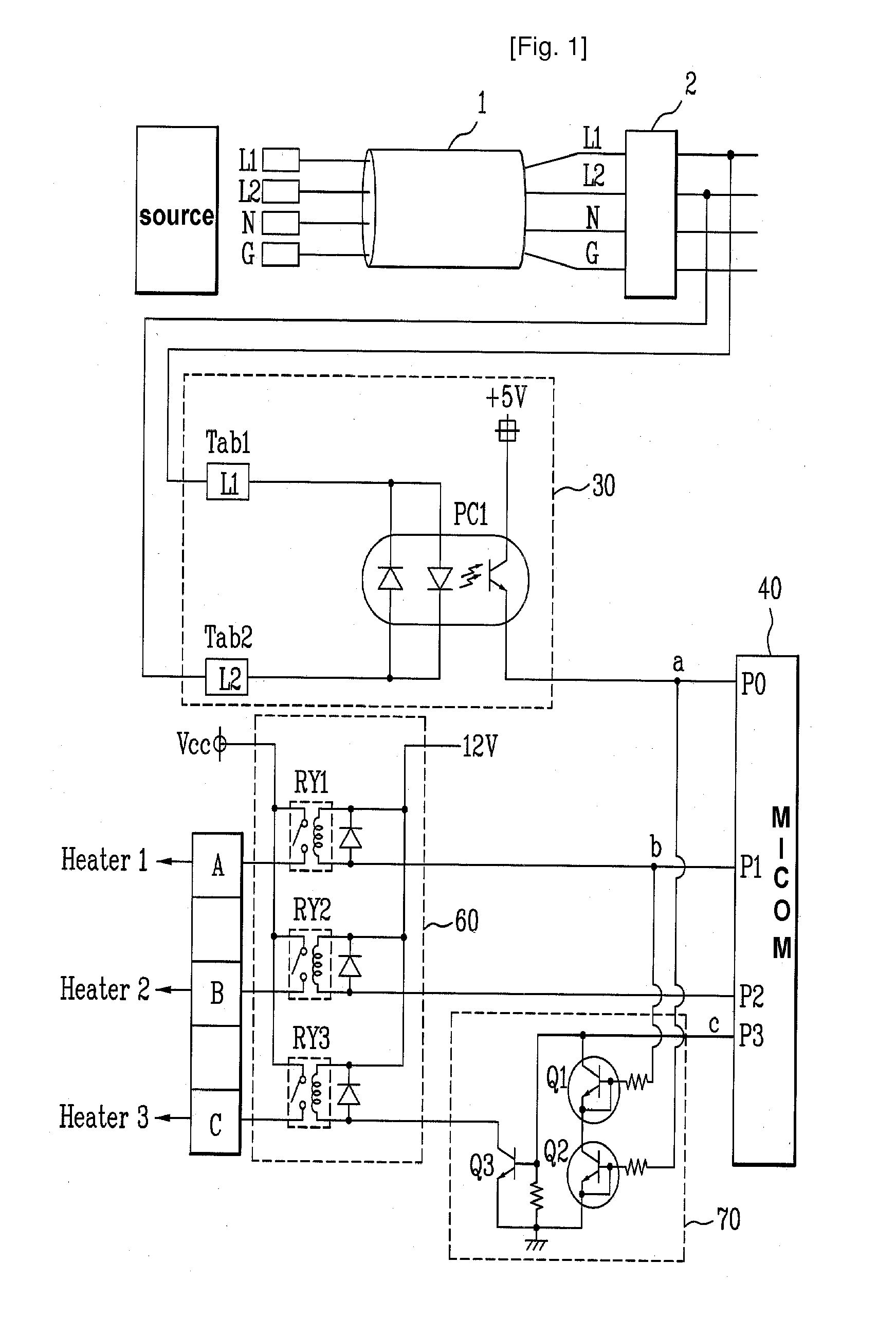
[0019]FIG. 1 is a circuit diagram of a current limiting device according to an embodiment of the present invention.

[0020]Referring to FIG. 1, a current limiting device of electric appliance includes at leas two heaters 1, 2, and 3, at least two relays RY1, RY2, and RY3 connected to the heater respectively to operate each of the heaters 1, 2, and 3, a sensing unit 31 connected to live lines L1 and L2 of a power cord 1 to sense the power types according to a potential difference of lines, a micom 40 controlling the relays RY1, RY2, and RY3 to selectively operate a heater within a standard value of an allowable current according to the power types detected through the power detecting unit 30, and a current limiting unit 70 limiting a part of heaters within a standard value of an allowable current by receiving the power types de...


PUM


Abstract

Provided is a device for limiting a current of electric appliance. The current limiting device includes: at least two loads; at least two load driving units connected to the loads to control applying power to the loads; a power detecting unit detecting a power type; a micom controlling the load driving unit according to the power type detected by the power detecting unit to drive the load using a current flowing into the load within an allowable value; and at least one current limiting unit connected to at least one control line connecting the micom and the load driving unit and limiting a current of the load driving unit connected to the control line when the micom malfunctions by using a control signal of the micom and a signal of the power type detected from the power detecting unit as an input signal.

Description

TECHNICAL FIELD[0001]The present invention relates to a device for limiting a current of electric appliance, and more particularly, to a device for limiting a current of electric appliance, the device more safely limiting an allowable current of electric appliance by satisfying standards according to input power types (single-phase, two-phase, and three-phase).BACKGROUND ART[0002]In a case of electric appliance requiring a high output, its total output is limited according to standards and power safety. That is, the total output of the electric appliance in a home power may be within an allowable current corresponding to standards of a power.[0003]For this, after the power type is determined by detecting the connection state of a power cord of a product, the total load of electronic appliance, and the total output for the total load are limited according to standards corresponding to the power types. That is, a total current amount is limited.[0004]More specifically, the power types...

Claims


Application Information

Patent Timeline
Patent Type & Authority Applications(United States)
IPC IPC(8): H02H7/20
CPCH02H3/05H02H9/02H02J3/14Y04S20/242Y04S20/222Y02B70/3266Y02B70/3225H02J2310/14Y02B70/30
Inventor JEONG, BYUNG JO
Owner LG ELECTRONICS INC
Why Eureka
Try Eureka