
Mixed Device for Controlling Power Transfer Between Two Cores of a Direct Current Network and Supplying an Alternating Current Motor

a technology of alternating current motor and direct current network, which is applied in the direction of motor/generator/converter stopper, electronic commutator, dynamo-electric converter control, etc., can solve the problems of system consisting of filter charge, new technology, and potential instability of the system

Inactive Publication Date: 2008-09-11
AIRBUS OPERATIONS (SAS) +1
View PDF9 Cites 13 Cited by
  • Summary
  • Abstract
  • Description
  • Claims
  • Application Information

AI Technical Summary

Benefits of technology

The invention is a device that combines two functions: controlling the power transfer between two cores of a direct current network and powering an alternating current engine. This device includes an assembly of two three-phase inverters and a module for controlling this assembly. The invention allows for a decentralized network architecture with stable cores and minimizes the cable lengths between the cores to ensure stability. The device also includes an LC-type filter to filter out harmonics generated by the equipment connected to the network. The technical effects of the invention include reducing instability risks and ensuring the quality and availability of power in normal and degraded modes.

Problems solved by technology

However, the implementation of such direct current networks presents new technical problems, in consideration in particular of the need to ensure the stability of these networks regardless of the type of charge supplied.
The document referenced [1] at the end of the description thus demonstrates that any system consisting of a filter charged by a static converter, which absorbs a constant power on the scale of the dynamics of the filter, is a potentially unstable system.
In consideration of the potential instability phenomena mentioned above, the propensity when very long cables are used to increase this phenomenon, it is therefore neither sufficient nor prudent to model the architecture of direct current networks on that of alternating current networks.

Method used


Image

  • Mixed Device for Controlling Power Transfer Between Two Cores of a Direct Current Network and Supplying an Alternating Current Motor
  • Mixed Device for Controlling Power Transfer Between Two Cores of a Direct Current Network and Supplying an Alternating Current Motor
  • Mixed Device for Controlling Power Transfer Between Two Cores of a Direct Current Network and Supplying an Alternating Current Motor

Examples


example embodiment

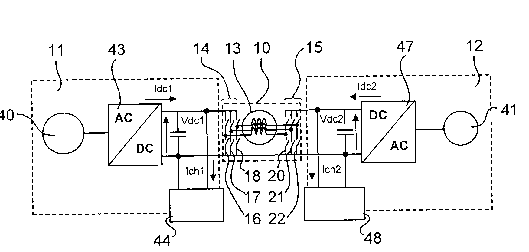
[0070]The engine 13 of the device of the invention is characterized by a maximum operation under a phase current Imax with an amplitude of 150A, as shown in FIG. 4A. The strategy for controlling the inverters 14 and 15 integrates, as a constraint, never exceeding this value, so as to ensure the safety of the engine 13 and the inverters 14 and 15. This strategy is not obligatory in the structure of the device of the invention and is presented here by way of an example. The addition of a homopolar component, which involves a direct current component Icont in the three phases of the engine, is therefore done here to the detriment of the amplitude of the sinusoidal component of the phase currents, as shown in FIG. 4A (the corollary of this choice is therefore a reduction in the mechanical power supplied by the engine).

[0071]The definition of the homopolar component of the current that passes through the device of the invention is in this case guided by the objective of balancing the pow...


PUM


Abstract

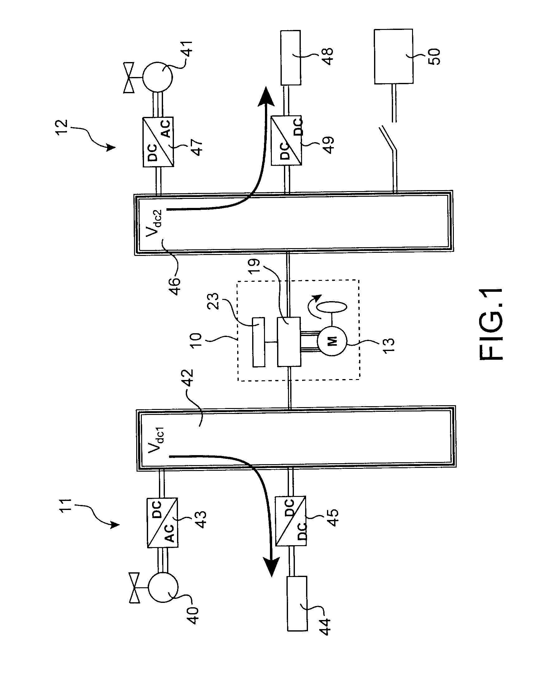
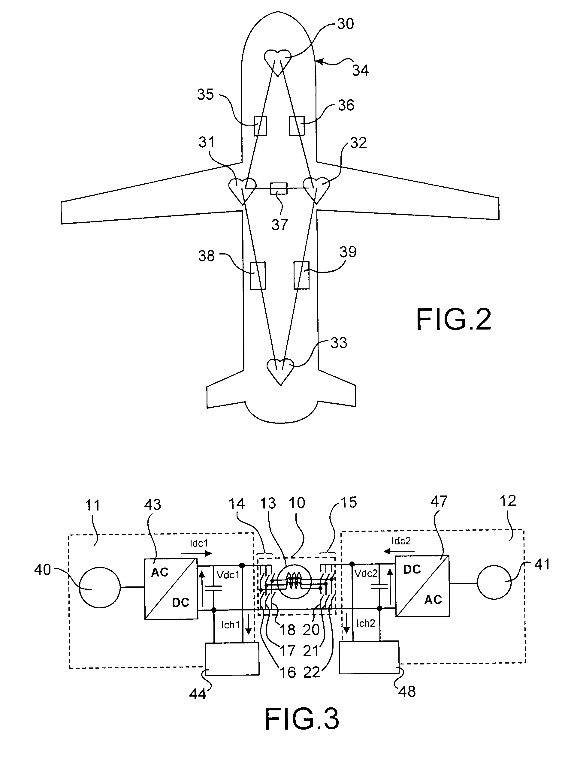
A combined device for instantaneous control of power transfer between two cores of a direct current network and for powering an alternating current engine. The device includes: an assembly of two three-phase inverters, each including three switching cells connected to the engine, which engine includes three stator windings connected to the two three-phase inverters, and a module for controlling the assembly, which ensures both an adjustable direct current power transfer and enables stabilization of the direct current voltage of one of the two cores if it is not connected, and the control of the engine.

Description

TECHNICAL FIELD[0001]This invention relates to a combined device for controlling the power transfer between two cores of a direct current network and for powering an alternating current engine.[0002]The field of the invention is in particular that of direct current networks on board an aircraft. However, the device of the invention can also be used with any type of on-board networks (naval, motor vehicle, etc.), and even networks not on board, for example in the field of stationary applications corresponding to a stationary network (direct current local network, railroad, etc.).[0003]To keep the description simple, we will limit it to the on-board aeronautical field.[0004]In the remainder of the description, the terms “continuous networks” and “direct current networks” have the same meaning and can therefore be used interchangeably.PRIOR ART[0005]The benefit of transferring energy by direct current connections in on-board networks is primarily due to the development of power electro...

Claims


Application Information

Patent Timeline
Patent Type & Authority Applications(United States)
IPC IPC(8): H02P27/06
CPCH02J1/10H02J1/14H02M3/33584Y02T50/54H02P25/025Y02T50/545H02P23/065H02P23/07H02P25/034H02J2310/44Y02T50/50
Inventor RAULIN, LOICPIQUET, HUBERTROBOAM, XAVIERFOCH, HENRIREGNIER, JEREMI
Owner AIRBUS OPERATIONS (SAS)
Learn More