
Imaging method, imaging apparatus, and driving device

Inactive Publication Date: 2008-09-11
SONY CORP
View PDF3 Cites 55 Cited by
  • Summary
  • Abstract
  • Description
  • Claims
  • Application Information

AI Technical Summary

Benefits of technology

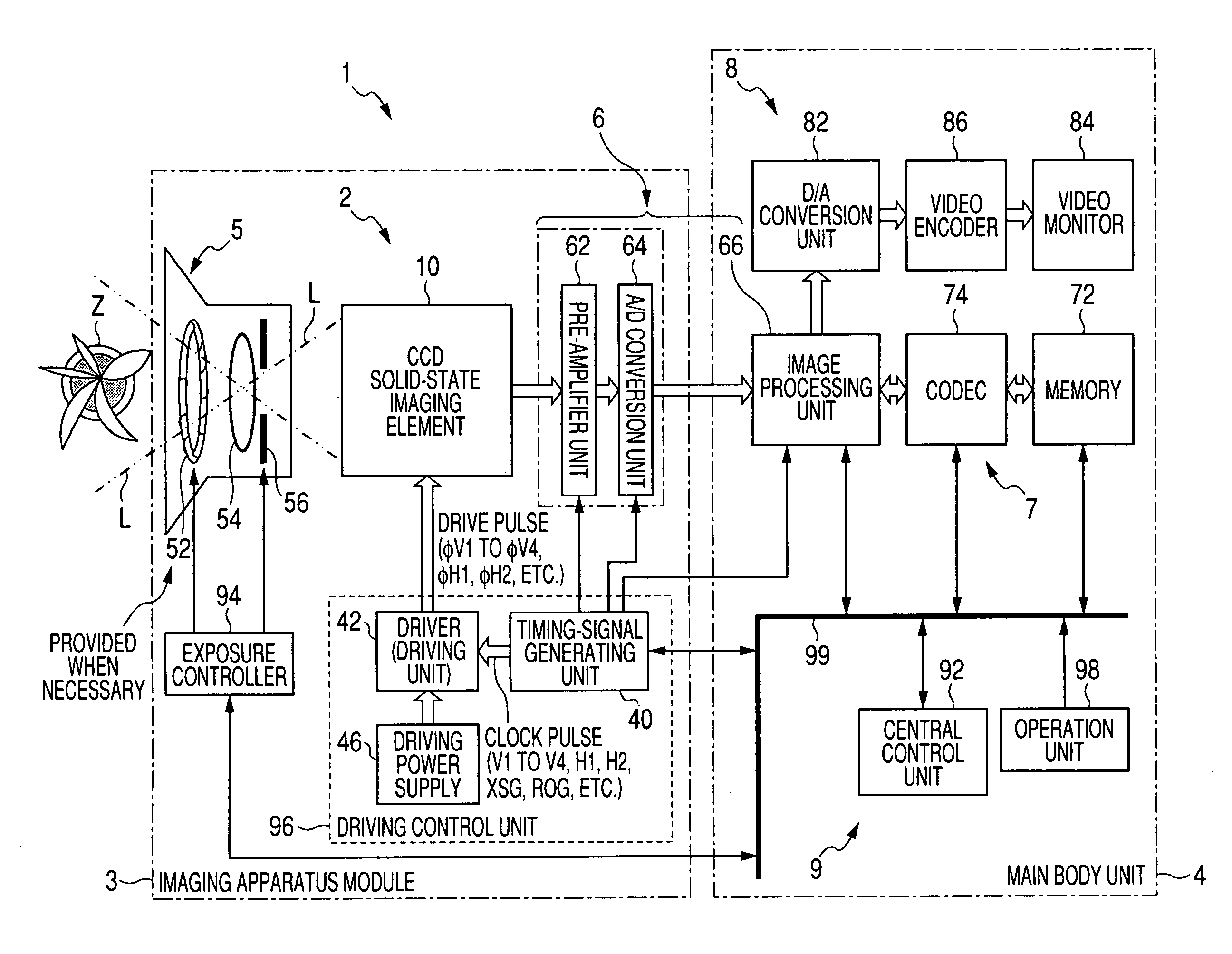
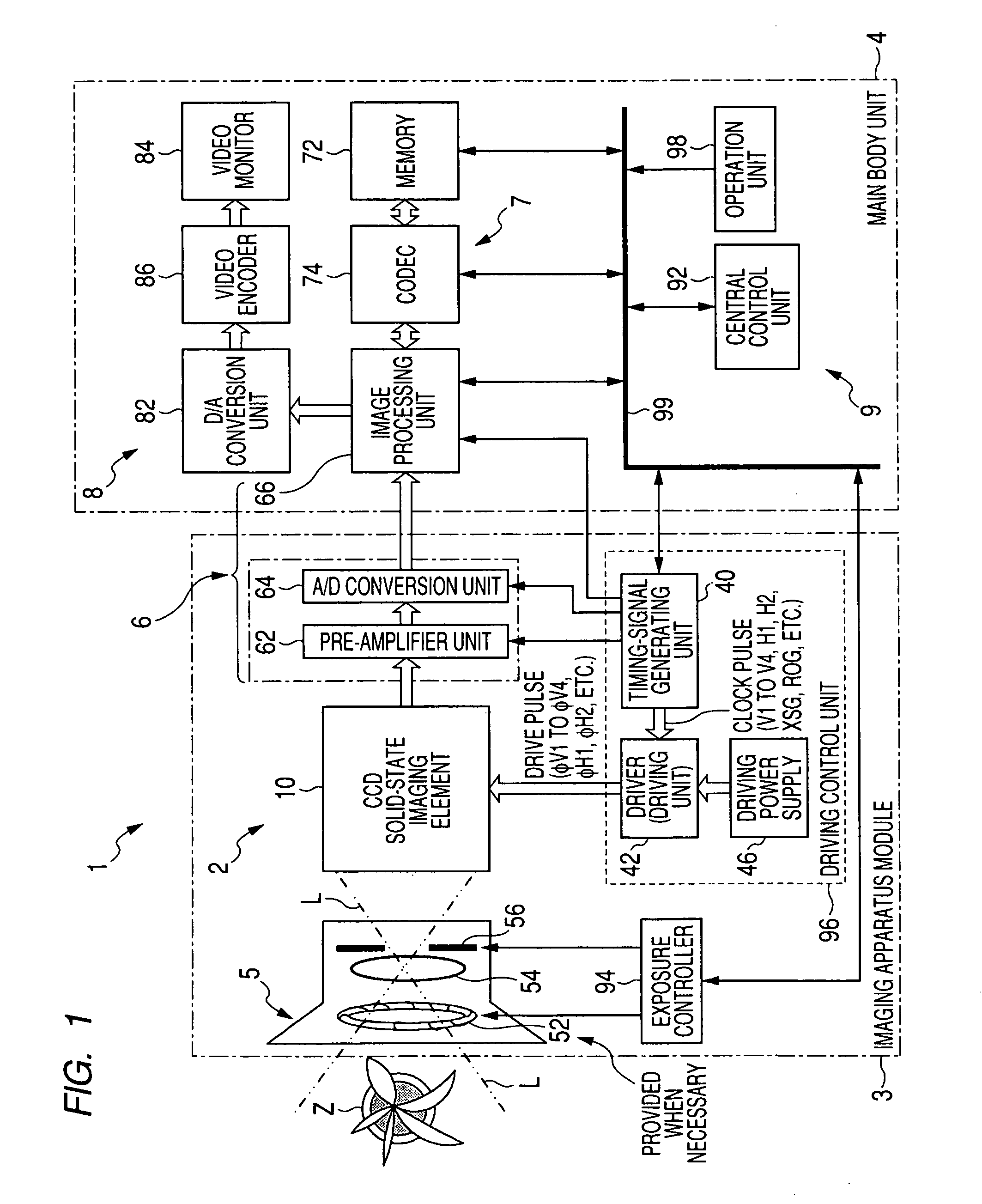
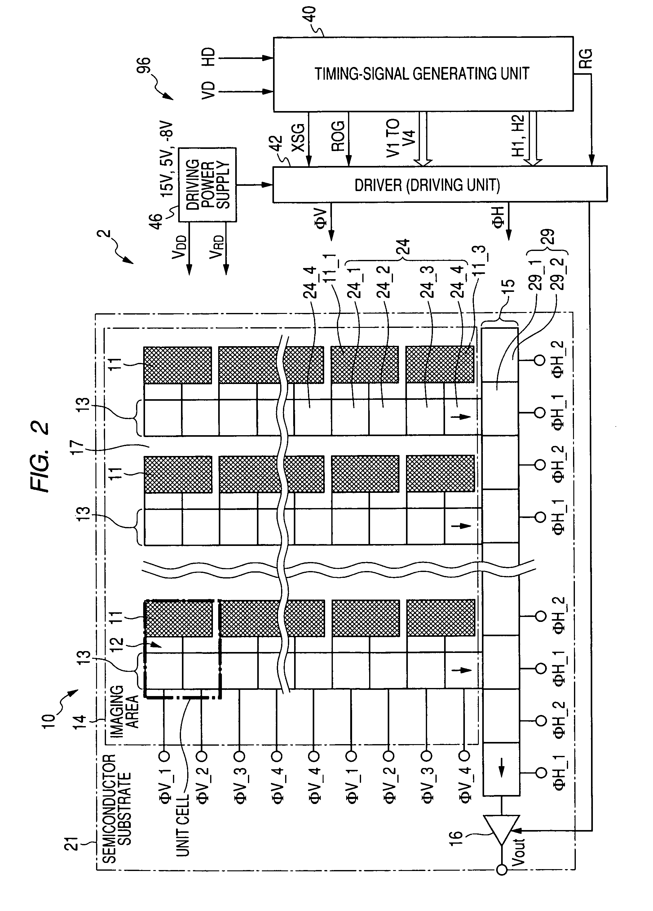
[0015]Therefore, it is desirable to provide a mechanism for solving the problem of unnecessary charge superimposition caused by leaving a signal charge read out to charge transfer sections stored without transferring the signal charges.
[0058]Consequently, concerning at least one of the high-sensitivity pixel signals and the low-sensitivity pixel signals, a phenomenon in which unnecessary charges such as a dark current component due to non-transfer of charges are superimposed on the signal charges read out from the charge generating sections to the charge transfer sections does not occur. Since the read-out signal charges are not left retained in the charge transfer sections, it is possible to reduce the dark current, reduce dot defects, and reduce a level of the defects.

Problems solved by technology

As a result, noise due to the unnecessary charges such as a dark current component occurs in both the high-sensitivity pixel signal and the low-sensitivity pixel signal, S / N falls, the blooming phenomenon is emphasized, and an extremely indistinct image is formed.

Method used


Image

  • Imaging method, imaging apparatus, and driving device
  • Imaging method, imaging apparatus, and driving device
  • Imaging method, imaging apparatus, and driving device

Examples


first embodiment

Modification to the First Embodiment

[0186]Concerning the driving control timing, it is also conceivable to carry out only the third method without carrying out the first method of line-shifting the signal charges for the low-sensitivity pixel signals, which are read out from the sensor sections 11l for low-sensitivity pixel signals to the vertical CCDs 13 earlier at the predetermined in the entire exposure period, to the horizontal CCD 15 for low-sensitivity pixel signals in “a part of the latter half or the entire latter half” of the electronic entire exposure period.

[0187]In this case, immediately after the final timing of the electronic entire exposure period, charge transfer of the signal charges for the low-sensitivity pixel signals read out earlier is started (t42). Since the CCD solid-state imaging device of the progressive scan system is used, as in FIGS. 9A to 9F showing a driving control method according to a modification to the first embodiment, signal charges are read ou...

second embodiment

Modification to the Second Embodiment

[0229]In the second embodiment, the IL-CCD or the FIT-CCD is adopted as the CCD solid-state imaging device 10. However, as shown in FIGS. 11A to 11G, it is also possible to use a CCD solid-state imaging device of the progressive scan system and using the mechanical shutter 52 and drive the CCD solid-state imaging device and the mechanical shutter 52 at the driving control timing according to the second embodiment.

[0230]In this case, as in the second embodiment, charge transfer of signal charges for the low-sensitivity pixel signals read out earlier is started after the mechanical shutter 52 is closed. Since the CCD solid-state imaging device of the progressive scan system is used, as in the modification to the first embodiment, after the mechanical shutter 52 is closed (t28), the signal charges are read out from the sensor section 11h for high-sensitivity pixel signals to the vertical CCDs 13 (t40). The read-out signal charges for the high-sensit...

third embodiment

Electronic Method of Forming a Sensitivity Pattern; Third Embodiment

[0234]FIGS. 12A to 12F are diagrams for explaining driving control according to a third embodiment of the present invention for electronically realizing a sensitivity mosaic pattern while controlling generation of a dark current in the vertical CCDs 13. FIGS. 13A to 13G are diagrams for explaining a modification (a first example) to the driving control method according to the third embodiment. FIGS. 14A to 14G are diagrams for explaining a modification (a second example) to the driving control method according to the third embodiment.

[0235]A driving control method according to the third embodiment and the modification (the first example) to the third embodiment are modifications to the driving control methods according to the second embodiment and the modification to the second embodiment. In the third embodiment and the modification (the first example), timing of a line-shift operation for all lines by short-time e...


PUM


Abstract

A driving device includes a driving control unit that reads out the signal charge generated by at least the charge generating section for a low-sensitivity pixel signal to the charge transfer section, after the predetermined timing, continues incidence of the electromagnetic wave and, after continuing the incidence of the electromagnetic wave, reads out the signal charge generated by at least the charge generating section for a high-sensitivity pixel signal to the charge transfer section, transfers the signal charge read out to the charge transfer section through the charge transfer section, and, concerning at least one of the signal charges for the high-sensitivity pixel signal and the low-sensitivity pixel signal, every time the signal charge is read out to the charge transfer section, transfers the signal charge read out to the charge transfer section through the charge transfer section without retaining the signal charge in the charge transfer section.

Description

CROSS-REFERENCES TO RELATED APPLICATIONS[0001]The present invention contains subject matter related to Japanese Patent Application JP 2007-058594 filed in the Japanese Patent Office on Mar. 8, 2007, the entire contents of which being incorporated herein by reference.BACKGROUND OF THE INVENTION[0002]1. Field of the Invention[0003]The present invention relates to an imaging method employing a solid-state imaging device (an image sensor) that images a subject and outputs an image signal corresponding to an image of the subject, a driving device that drives the solid-state imaging device, and a solid-state imaging apparatus and an imaging apparatus (camera systems) that carries out the imaging method such as an electronic still camera and an imaging apparatus module including the solid-state imaging device and the driving device. More specifically, the present invention relates to a technique for improving a dynamic range of an imaged subject image.[0004]2. Description of the Related Ar...

Claims


Application Information

Patent Timeline
IPC IPC(8): H04N5/228H01L27/148H04N5/335H04N5/341H04N5/353H04N5/355H04N5/361H04N5/3728
CPCH04N5/2353H04N5/35563H04N2209/045H04N9/045H04N5/372H04N23/73H04N25/585H04N25/71H04N25/70H04N25/136H04N23/843H04N25/134
Inventor HARADA, KOUICHIKOBAYASHI, ATSUSHIKOBAYASHI, SEIJIMITSUNAGA, TOMOOONO, HIROAKI
Owner SONY CORP
Learn More