
Relay apparatus, path selection system, path selection method and program

a path selection and relay technology, applied in the field of communication technology, can solve problems such as complicated practice for setting/changing the appliance in which the path control protocol operates in conformity with the band of bottlenecks

Inactive Publication Date: 2008-09-11
NEC CORP
View PDF4 Cites 23 Cited by
  • Summary
  • Abstract
  • Description
  • Claims
  • Application Information

AI Technical Summary

Benefits of technology

[0219]Next, the effects of this exemplary embodiment will be explained.
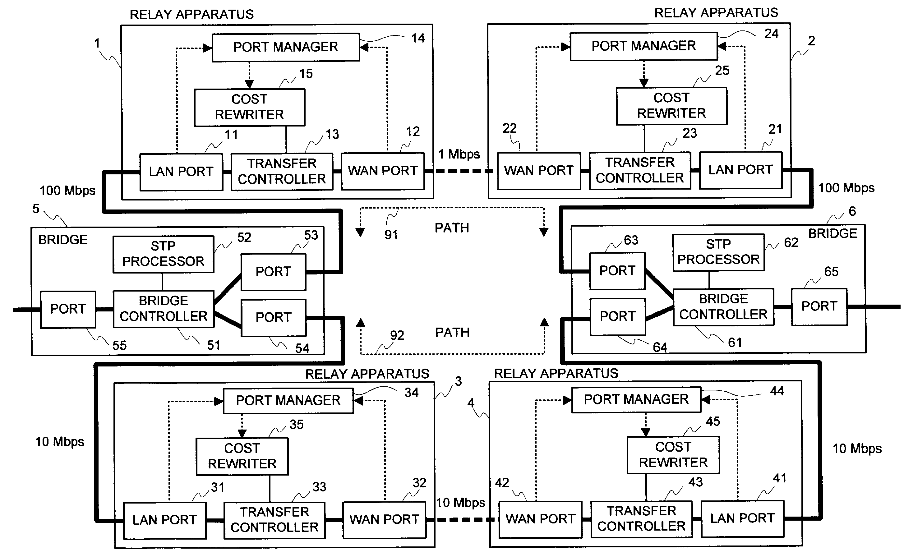
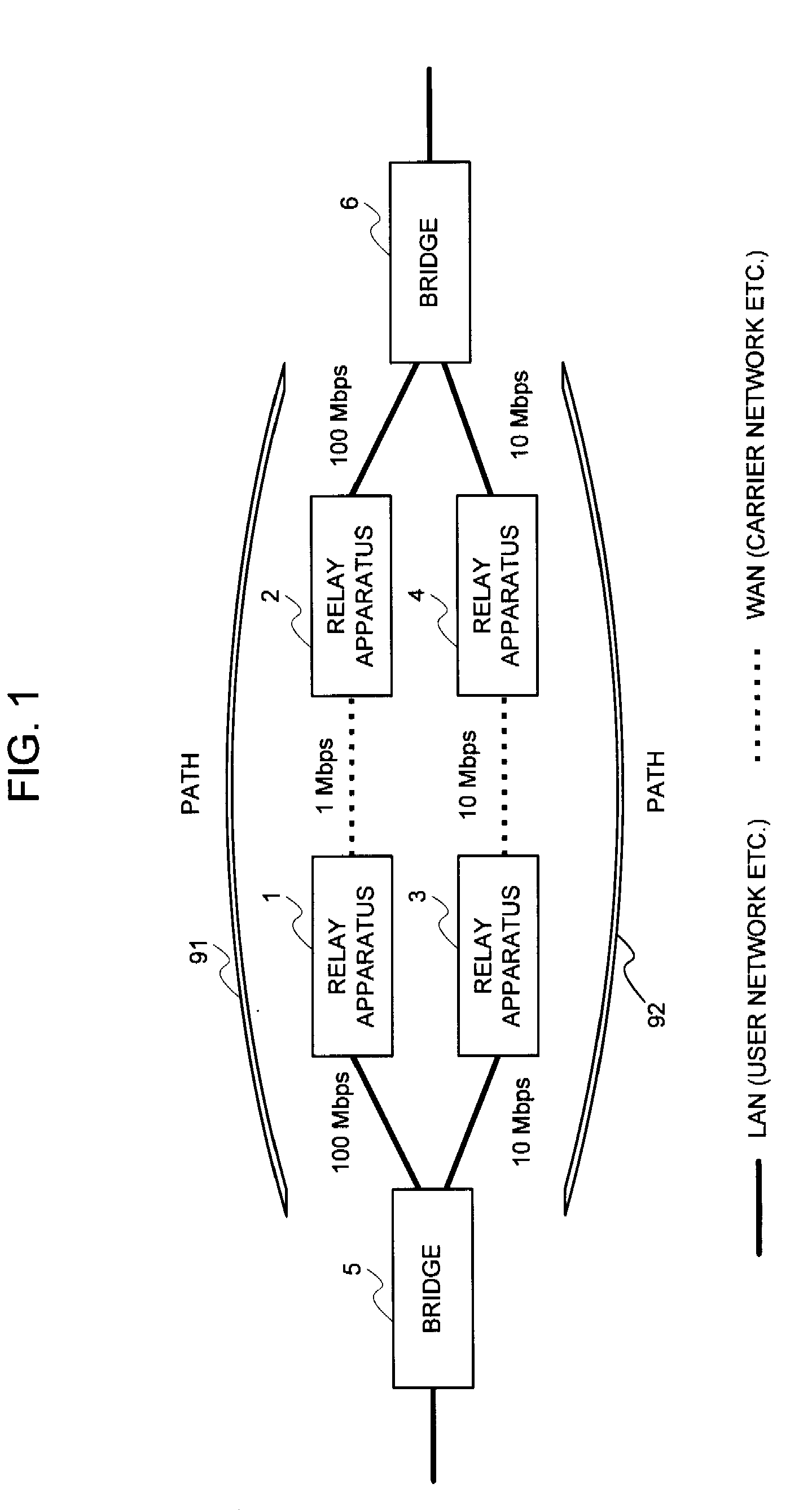
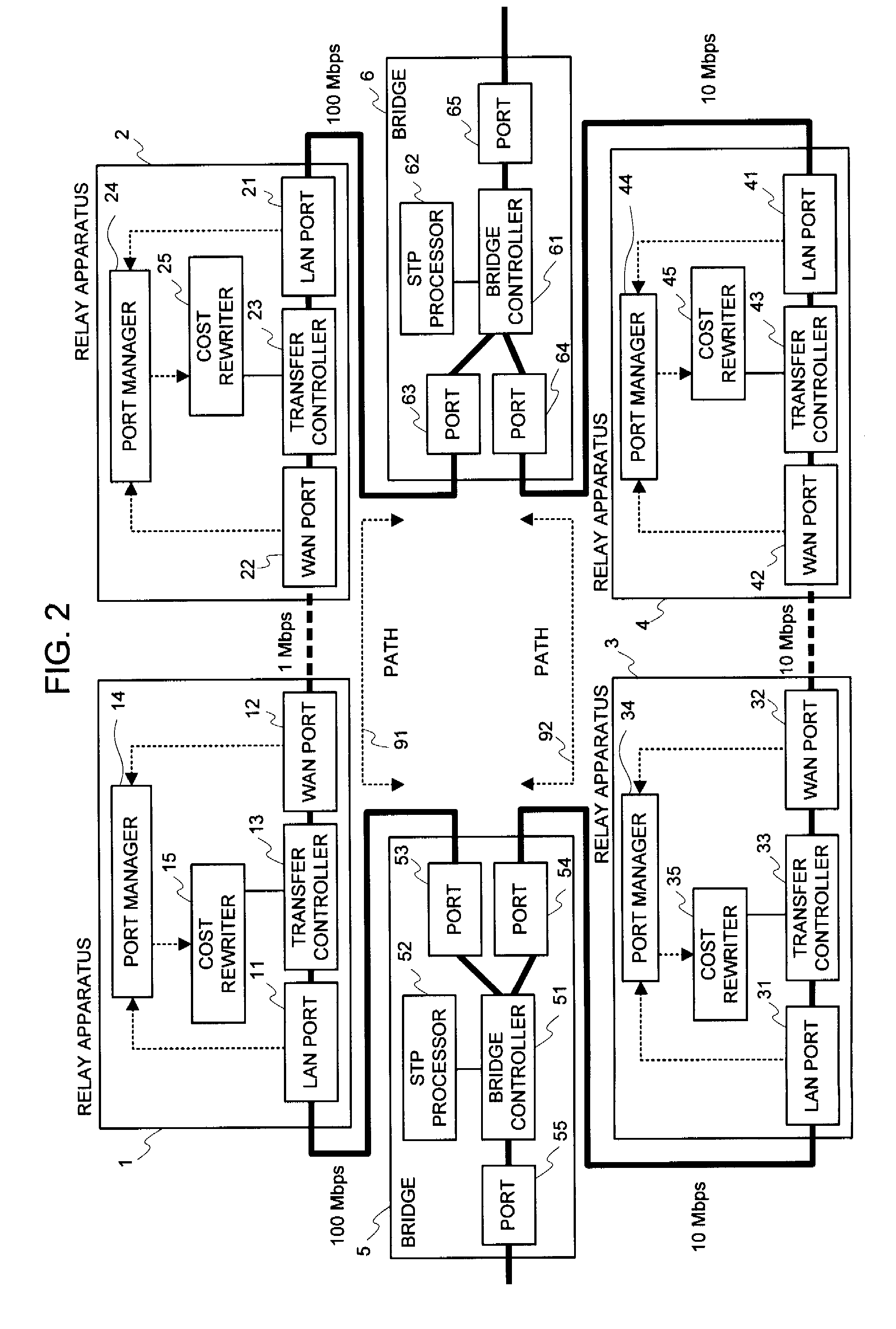
[0220]Utilizing the invention listed in this exemplary embodiment makes it possible to reflect a band of the bottleneck into the cost, to select an optimal path, and to enhance an efficiency of the net utilization without making a setting or a modification to the apparatus (bridge etc.) in which the path control protocol operates in a case where a difference exists between an actually utilizable rate (a band of the bottleneck) in the path between the bridges etc. and a link rate of the connection link such as the bridge etc. in a net in which the apparatus (bridge etc.), in which the path control protocol (STP etc.) for automatically computing a cost of a link by a physical band of the connection link operates, exists.
[0221]The reason is that in the relay apparatus (a transmission apparatus, a tunnel apparatus, or the like) that is inserted between the bridges etc., the port manager within the relay apparatus, upon receipt of a link rate from the port, investigates which side, out of the WAN side and the LAN side, becomes a bottleneck, and the cost rewriter within the relay apparatus rewrites the root path cost field within the BPDU in conformity to the rate of the bottleneck.A Second Exemplary Embodiment
[0222]In the second exemplary embodiment of the present invention, in a case where a difference exists between an actually utilizable rate (a band of the bottleneck) in the path between the bridges etc. and a link rate of the connection link such as the bridge etc. in a net in which the apparatus (bridge etc.), in which the path control protocol (STP etc.) for automatically computing a cost of a link by a physical band of the connection link operates, exist, the relay apparatus (a transmission apparatus, a tunnel apparatus, or the like) that is inserted between the bridges etc., upon receipt of a link rate from the port, investigates which side, out of the WAN side and the LAN side, becomes a bottleneck, and rewrites the root path cost field within the BPDU in conformity to the rate of the bottleneck by snooping the BPDU, thereby allowing a band of the bottleneck to be reflected into the cost, an optimal path to be selected, and an efficiency of the net utilization to be enhanced without making a setting or a modification to the apparatus (bridge etc.) in which the path control protocol operates.
[0223]In addition hereto, the above-mentioned relay apparatus notifies the latest rate of the bottleneck of its own to the relay apparatus facing it, and further receives information of the rate of the bottleneck from the relay apparatus facing it, thereby allowing the relay apparatus for rewriting the root path cost to know a band of the bottleneck also in a case where no bottleneck exists in the connection link of the relay apparatus for rewriting the root path cost, which enables an actually utilizable rate (a band of the bottleneck) in the path between the bridges etc. to be reflected into the cost, an optimal path to be selected, and an efficiency of the net utilization to be enhanced.
[0224]The second exemplary embodiment of the present invention differs from the first exemplary embodiment in a point that a rate notifier is added to the configuration of the first exemplary embodiment, the rate notifier notifies the latest rate of the bottleneck of its own to the relay apparatus facing its own relay apparatus, and the port manager takes the notified rate of the bottleneck into consideration and gives an instruction for rewriting the cost.

Problems solved by technology

(2) The practice for setting / changing the appliance in which the path control protocol operates in conformity to the band of the bottleneck is complicated.

Method used


Image

  • Relay apparatus, path selection  system, path selection method and program
  • Relay apparatus, path selection  system, path selection method and program
  • Relay apparatus, path selection  system, path selection method and program

Examples


first exemplary embodiment

[0095]In the first exemplary embodiment of the present invention, in a net in which the apparatus (bridge etc.) in which a path control protocol (STP etc.) for automatically computing a cost of a link by a physical band of the connection link operates exists, in a case where a difference exists between an actually utilizable rate (a band of the bottleneck) in the path between the bridges etc. and a link rate of the connection link such as the bridge etc., the relay apparatus (a transfer apparatus, a tunnel apparatus, or the like) that is inserted between the bridges etc., upon receipt of a notification of the link rate from the port, investigates which side, out of the WAN side and the LAN side, becomes a bottleneck, and in addition hereto, snoops the BPDU to rewrite the root path cost field within the BPDU in conformity to the rate of the bottleneck, thereby allowing the band of the bottleneck to be reflected into the cost, an optimal path to be selected, and an efficiency of the n...

second exemplary embodiment

A Second Exemplary Embodiment

[0222]In the second exemplary embodiment of the present invention, in a case where a difference exists between an actually utilizable rate (a band of the bottleneck) in the path between the bridges etc. and a link rate of the connection link such as the bridge etc. in a net in which the apparatus (bridge etc.), in which the path control protocol (STP etc.) for automatically computing a cost of a link by a physical band of the connection link operates, exist, the relay apparatus (a transmission apparatus, a tunnel apparatus, or the like) that is inserted between the bridges etc., upon receipt of a link rate from the port, investigates which side, out of the WAN side and the LAN side, becomes a bottleneck, and rewrites the root path cost field within the BPDU in conformity to the rate of the bottleneck by snooping the BPDU, thereby allowing a band of the bottleneck to be reflected into the cost, an optimal path to be selected, and an efficiency of the net ...

third exemplary embodiment

A Third Exemplary Embodiment

[0312]In the second exemplary embodiment of the present invention, the rate of the WAN line, which was acquired from the link-up rate in the WAN PORT 12, the WAN PORT 22, the WAN PORT 32, and the WAN PORT 42, was is utilized for computing the cost, whereas the third exemplary embodiment of the present invention differs from the second exemplary embodiment in a point of providing a rate delay measurer 17, a rate delay measurer 27, a rate delay measurer 37, and a rate delay measurer 47, acquiring the rate of the WAN line by transmitting / receiving a measurement frame, and computing the cost.

[0313]This makes it possible to accurately obtain the cost also in a case where the link rate of the WAN line fluctuates.

[0314](Explanation of a Configuration)

[0315]A configuration in this exemplary embodiment will be explained by making a reference to FIG. 9.

[0316]In third exemplary embodiment of the present invention, a rate delay measurer is added to the configuration ...


PUM


Abstract

An object of the present invention is to reflect a band of the bottleneck into the cost, to select an optimal path, and to enhance an efficiency of the net utilization without making a setting or a modification to the apparatus (bridge etc.) in which the path control protocol operates in a case where a difference exists between an actually utilizable rate (a band of the bottleneck) in the path between the bridges etc. and a link rate of the connection link such as the bridge etc. in a net in which the apparatus (bridge etc.), in which the path control protocol (STP etc.) for automatically computing a cost of a link by a physical band of the connection link operates, exists. In the system of the present invention, the port manager within the relay apparatus, upon receipt of a notification of the link rate from the port, investigates which side, out of the WAN side and the LAN side, becomes a bottleneck, and the cost rewriter within the relay apparatus rewrites the root path cost field within the BPDU in conformity to the rate of the bottleneck.

Description

INCORPORATION BY REFERENCE[0001]This application is based upon and claims the benefit of priority from Japanese patent application No. 2007-056643, filed on Mar. 7, 2007, the disclosure of which is incorporated herein in its entirety by reference.RELATED ART[0002]The present invention relates to a communication technology for enhancing a reliability by providing path redundancy, and more particularly to a technology of, in a net in which an apparatus (bridge etc.) in which a path control protocol (STP etc.) for automatically computing a cost of a connection link by a physical band of the connection link operates exists, reflecting a band of a bottleneck into the cost, selecting an optimal path, and enhancing a net utilization efficiency without making a setting or a modification to the apparatus (bridge etc.) in which the path control protocol operates in a case where a difference exists between an actually utilizable rate (a band of the bottleneck) in the path between the bridges e...

Claims


Application Information

Patent Timeline
IPC IPC(8): H04J3/16H04L45/851H04L47/20H04L12/46
CPCH04L45/04H04L45/124H04L45/125H04L45/48H04L45/66H04L45/484H04L45/02
Inventor ENOMOTO, NOBUYUKITAKAGI, KAZUO
Owner NEC CORP
Learn More