
Non-imaging tracking tools and method for hip replacement surgery

Active Publication Date: 2008-09-11
KINAMED
View PDF62 Cites 3 Cited by
  • Summary
  • Abstract
  • Description
  • Claims
  • Application Information

AI Technical Summary

Benefits of technology

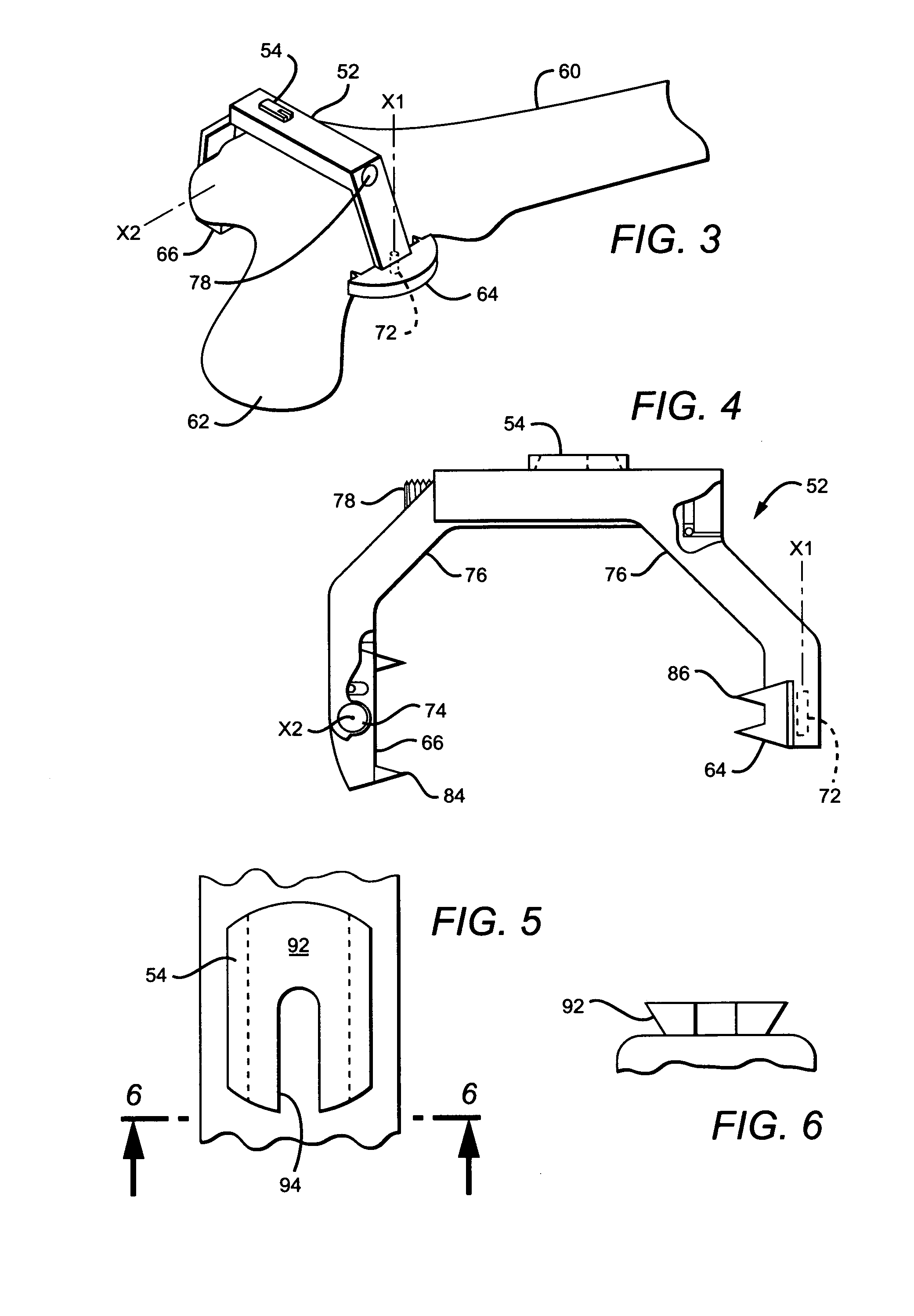
[0013]The invention also includes a surgical tool for mounting a trackable target to a bone, suitable for fixation to a human femur. The tool includes a removable bone clamp and a releasable coupling member, integrated with said removable bone clamp. The coupling member is arranged to mate with a compatible coupling member mounting the trackable target to establish a predetermined spatial relationship between said bone clamp and said trackable target. Furthermore, the coupling member includes a releasable connection between said target and said bone clamp, to remove said trackable target. The connection is capable of re-engaging in a re-engaged position which accurately recaptures said spatial relationship between the bone and said trackable target.

Problems solved by technology

Many of the procedures will eventually require revision, due to one of any number of problems.
Problems can arise with the implant, which can wear, degrade or even fracture.
In other cases, dislocation of the replaced hip can occur, causing extreme pain (not to mention inconvenience and expense).
In spite of the published research, the typical surgeon has not adopted any sophisticated method of navigating hip replacement surgery, in spite of the availability of several techniques.
This method fails to consider the considerable movement and variation in the patient's pelvic position during surgery; at worst it aligns the shell with the operating table (not necessarily the pelvis).
DiGioia's method begins with extensive pre-operative imaging, including relatively expensive CT scanning.
The method of DiGioia et al. is complex and requires sophisticated digital and radiological techniques.
It is frequently found that physicians are loath to adopt any methods, and particularly any computerized methods, which are unduly complex, expensive or time consuming.

Method used


Image

  • Non-imaging tracking tools and method for hip replacement surgery
  • Non-imaging tracking tools and method for hip replacement surgery
  • Non-imaging tracking tools and method for hip replacement surgery

Examples


Embodiment Construction

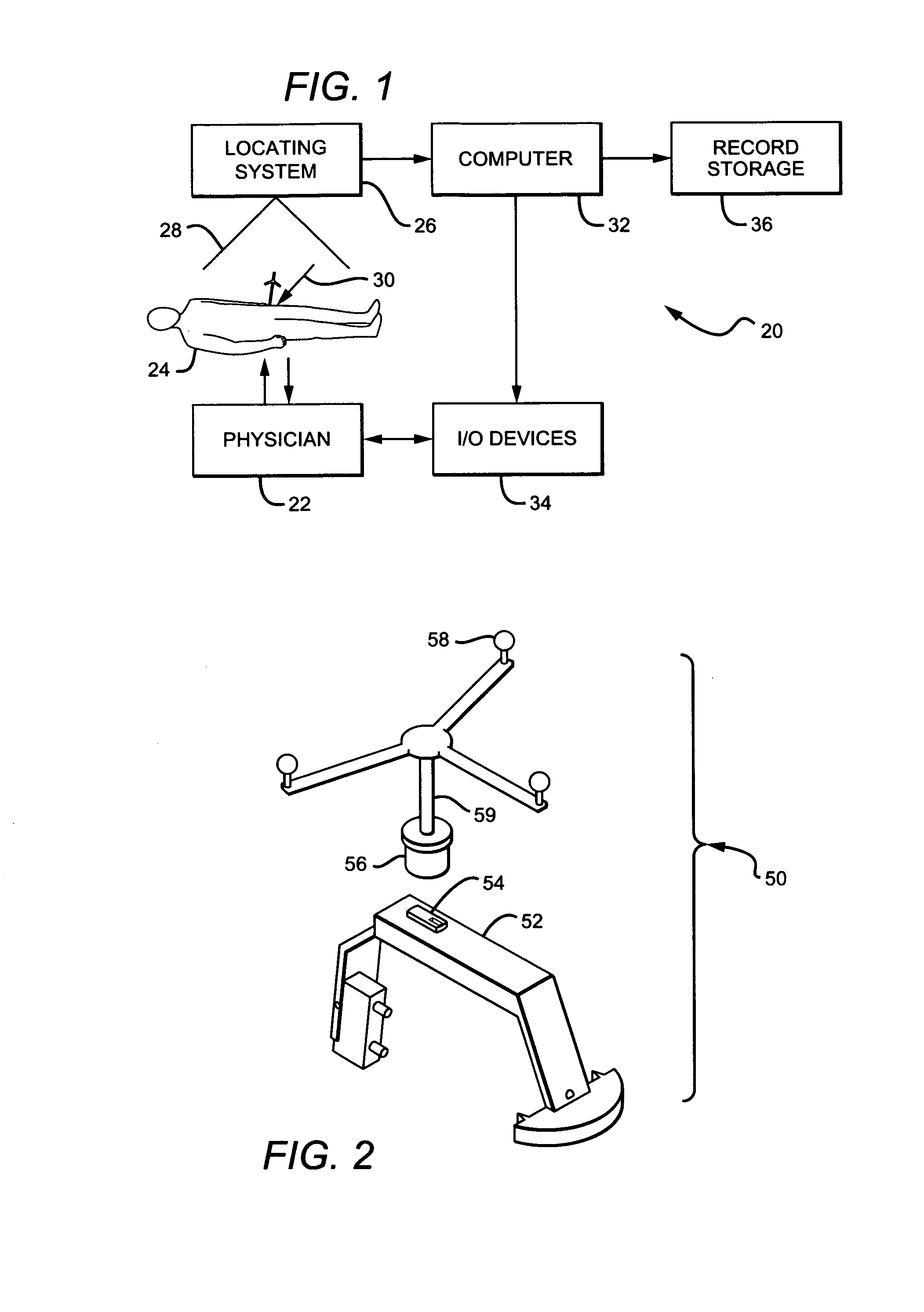
[0027]FIG. 1 shows a system-level block diagram of a system or apparatus 20 which provides the environment in which the present invention operates. The system or apparatus 20 is generally a computer aided system for navigating orthopedic surgery. A physician or other professional 22 performs a hip surgery (for example, total hip replacement) on a patient 24. An optical or equivalent locator or locating system 26 is disposed near the patient, so that the operating field is encompassed substantially within the field of view 28 of the locator 26. A suitable optical locator is available commercially, for example the “Polaris” available from Northern Digital Inc., in Waterloo, Ontario, Canada. Optical trackers or markers 30 are used during the operation, as more fully described in related application U.S. Ser. No. 10 / 075,796. The markers 30 allow the locator 26 to acquire the positions and orientations of tools and anatomical reference points, as described below.

[0028]The optical locator...


PUM


Abstract

The invention includes a method of determining a surgical patient's pelvic position and inputting that position into a computer via a tracking system, suitable for use in navigating partial or total hip replacement surgery. The patient is first aligned with anatomical reference points in relation to corresponding locating features on a patient positioner. The positions of index features on the patient positioner are then acquired via a tracking system. Based on the positions of the index features and their known relationship to the locating features, the locations of the anatomical reference features are calculated and a pelvic plane is defined therefrom. The invention also includes a surgical tool for mounting a trackable target to a human bone, suitable for fixation to a human femur. This tool includes a removable bone clamp and a releasable coupling member, integrated with said removable bone clamp.

Description

[0001]This application is a divisional of and claims priority of U.S. application Ser. No. 10 / 637,304 filed on Aug. 8, 2003 in the United States Patent Office.BACKGROUND OF THE INVENTION[0002]1. Field of the Invention[0003]This invention relates to computer assisted surgery generally and more specifically to computer assisted total hip replacement (THR) or hip arthroplasty operations.[0004]2. Description of the Related Art[0005]Total hip replacement or arthroplasty operations have become increasingly common in the United States, with more than 300,000 such operations occurring annually. Many of the procedures will eventually require revision, due to one of any number of problems. Problems can arise with the implant, which can wear, degrade or even fracture. In other cases, dislocation of the replaced hip can occur, causing extreme pain (not to mention inconvenience and expense). The incidence of dislocation has remained at approximately 2-6 percent, in spite of improvements to techn...

Claims


Application Information

Patent Timeline
IPC IPC(8): A61B17/56A61BA61B19/00A61F2/00A61F5/04
CPCA61B17/1742A61B19/203A61B19/50A61B19/5244A61B2017/00477Y10T24/44598A61B2019/502A61B2019/505A61B2019/5255A61B2019/5272A61B2019/5483A61B2019/461A61B2090/3983A61B2034/102A61B2034/2055A61B2034/2072A61B34/20A61B90/14A61B2090/061A61B34/10A61B2034/105
Inventor SARIN, VINEET KUMARBRUCE, ROBERT A.PRATT, WILLIAM RALPHPRATT, CLYDE RONALDCARIGNAN, ROGER C.
Owner KINAMED
Learn More