Internal tourniquet system

a technology of internal tourniquets and tourniquets, which is applied in the field of wearing apparel, can solve the problems of users being more likely to suffer severe laceration in the extremities, not always available medical care, etc., and achieve the effect of maintaining the smooth appearance of the user's garment, and enhancing the comfort of users

Inactive Publication Date: 2008-09-11
SALANG LLC
View PDF5 Cites 25 Cited by
  • Summary
  • Abstract
  • Description
  • Claims
  • Application Information

AI Technical Summary

Benefits of technology

[0015]An object of this invention is to provide a garment having a total of eight tourniquets incorporated into the inner surface of the garment with webbing that is non-chafing and light; an object of this invention is to have tourniquets incorporated into the inner surface of the garment at strategic locations requiring the least amount of pressure applied to result in the lowest amount of blood loss from the extremity; an object of this invention is to provide a garment having tourniquets incorporated into the inner surface of the garment with flaps available at the site of each tourniquet's tightening and securing mechanism in order to allow for easy access to the tourniquet, to protect the tightening and securing mechanism from the environment during non-use and to maintain the smooth appearance of the user's garment. An object of this invention is to provide a garment with an additional lever or bar, while continuing to maintain the smooth appearance of the user's garment, to allow additional torque to be applied by the injured user or second party if necessary

Problems solved by technology

Unfortunately, medical care is not always immediately available and the user or his buddy has to tend to his own or his friend's wounds.
The users have armor that protects their torsos; however, since the extremities are left unprotected the users are more likely to suffer a severe laceration in those extremities.

Method used


Image

  • Internal tourniquet system
  • Internal tourniquet system
  • Internal tourniquet system

Examples


Embodiment Construction

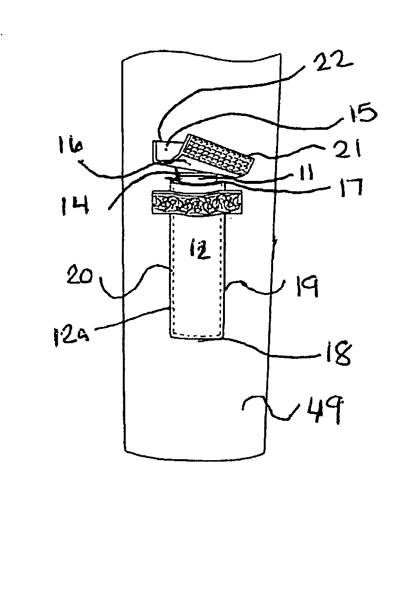
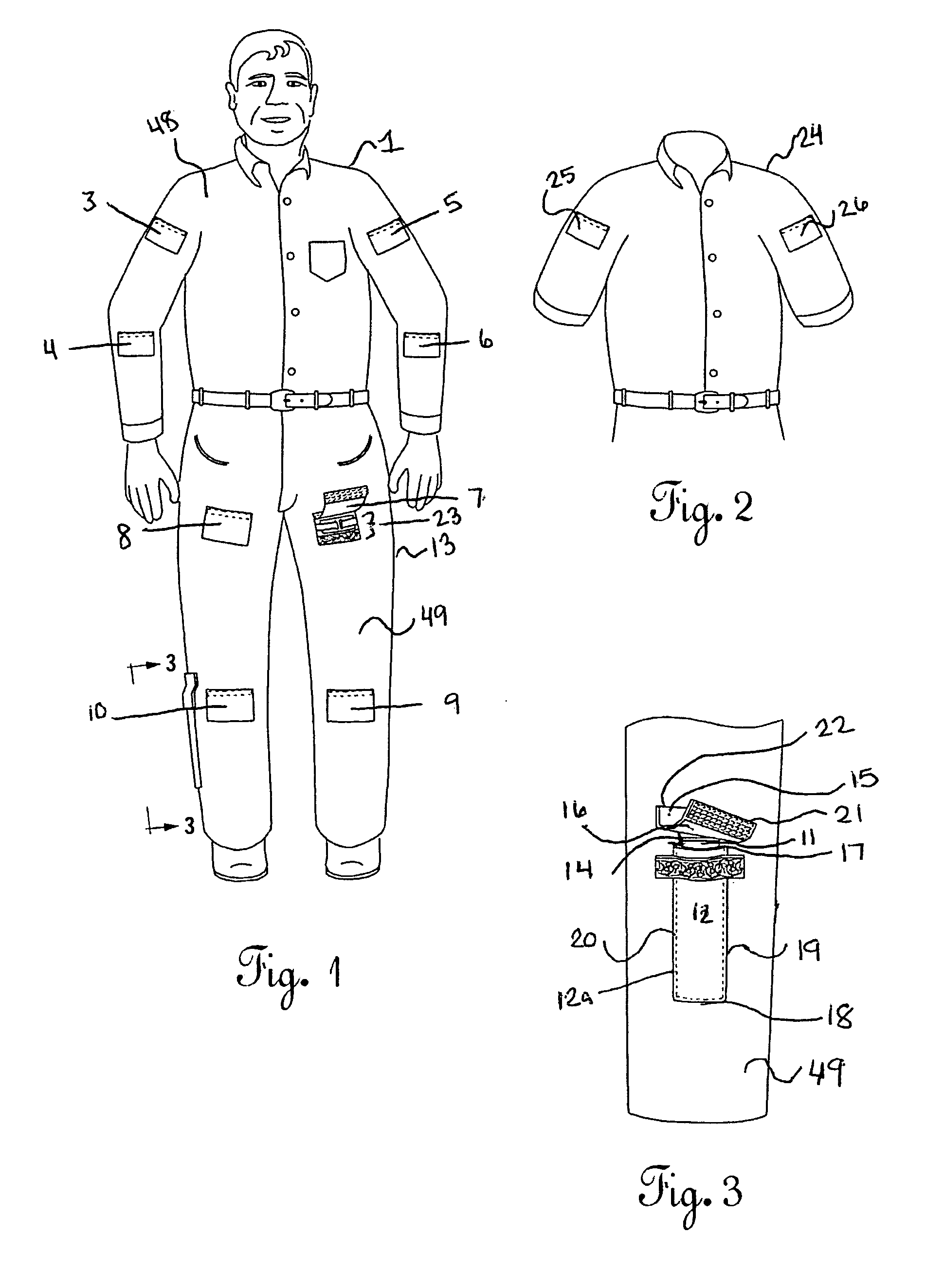
[0028]FIGS. 1 through 10 illustrate particular embodiments of the internal tourniquet system that is the current invention. FIG. 1 depicts the preferred embodiment of the current invention in a garment that comprises a full-sleeved, button-down shirt 1 with exterior surface 48 and two-pocket pants 13 with exterior surface 49. It is understood that the shirt 1 is merely for exemplary purposes and the garment could be of other types depending on the needs of the person in a high risk activity. For instance the garment might take the form of a various garments such as a flight suit, diving or swimming wet suit, battlefield outerwear, fire fighter outerwear or police outerwear.

[0029]The shirt 1 and pants 13 preferably include a total of eight flaps 3,4,5,6,7,8,9,10 for accessing the internal tourniquet system but could include more or less flaps and tourniquets. The flaps are releasable secured to the garment by hook and loop fasters or other suitable quick release connectors. Flaps 3 a...


PUM


Abstract

An internal tourniquet system may comprise as many as eight tourniquets strategically positioned, two per extremity, so as to optimize the inversely proportional relationship between the force applied to the tourniquet and the blood flow from the laceration on the extremity farther from the body than the positioned tourniquet. Each garment is equipped with internal channels to position the tourniquets and each garment is equipped with removable covering flaps for ease of access to the tightening and securing mechanism on the tourniquets. Each garment may also be supplied with a lever or bar and a storage location on the garment in order to apply more torque if necessary to the tourniquet banded site. And each garment may also be supplied with such flaps that are able to secure the lever or bar in position, once to blood flow has ceased to an acceptable level.

Description

CROSS-REFERENCE TO RELATED APPLICATIONS[0001]N / ASTATEMENTS REGARDING FEDERALLY SPONSORED RESEARCH OR DEVELOPMENT[0002]N / AREFERENCE TO A MICROFICHE APPENDIX[0003]N / ABACKGROUND OF THE INVENTION[0004]1. Field of the Invention[0005]This invention generally relates to wearing apparel and particularly to garments and garments worn by users engaged in hazardous occupations or activities and where injury to the extremities is a possibility.[0006]2. Description of the Related Art[0007]The current tourniquet system is carried by a user or a medic for a group of users, or other groups in hazardous conditions; however, in this configuration, the entire group has to stay within each other's sightline and the hazardous area must remain small. In addition, the medic himself cannot be injured or the first aid kit lost or destroyed.[0008]In addition, U.S. Pat. No. 2,702,551 issued to G. G. Hobson on Feb. 22, 1955 discloses garments with one tourniquet per extremity equipped to the outside of the gar...

Claims


Application Information

Patent Timeline
Patent Type & Authority Applications(United States)
IPC IPC(8): A61B17/00
CPCA61B17/1322
Inventor ROSE, KEITH J.
Owner SALANG LLC
Why Eureka
Try Eureka