Freefall pyrolytic oven

Active Publication Date: 2008-09-18
SIMEKEN
View PDF15 Cites 41 Cited by
  • Summary
  • Abstract
  • Description
  • Claims
  • Application Information

AI Technical Summary

Problems solved by technology

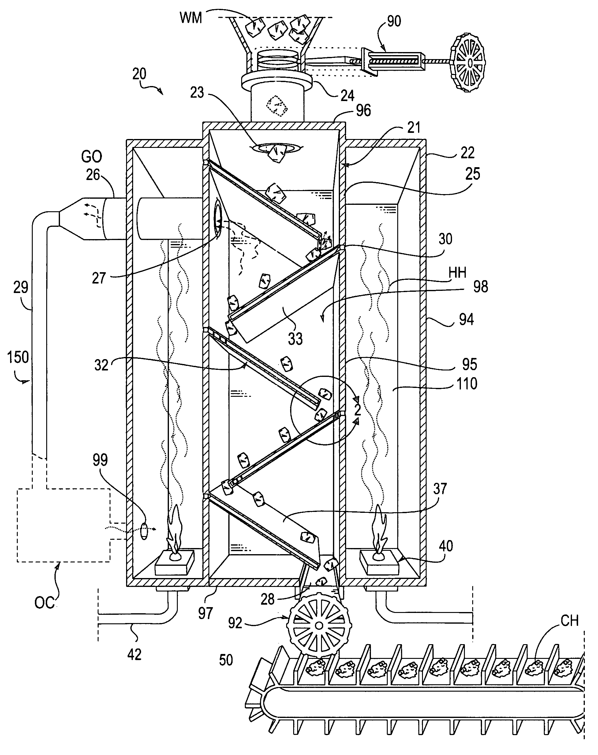
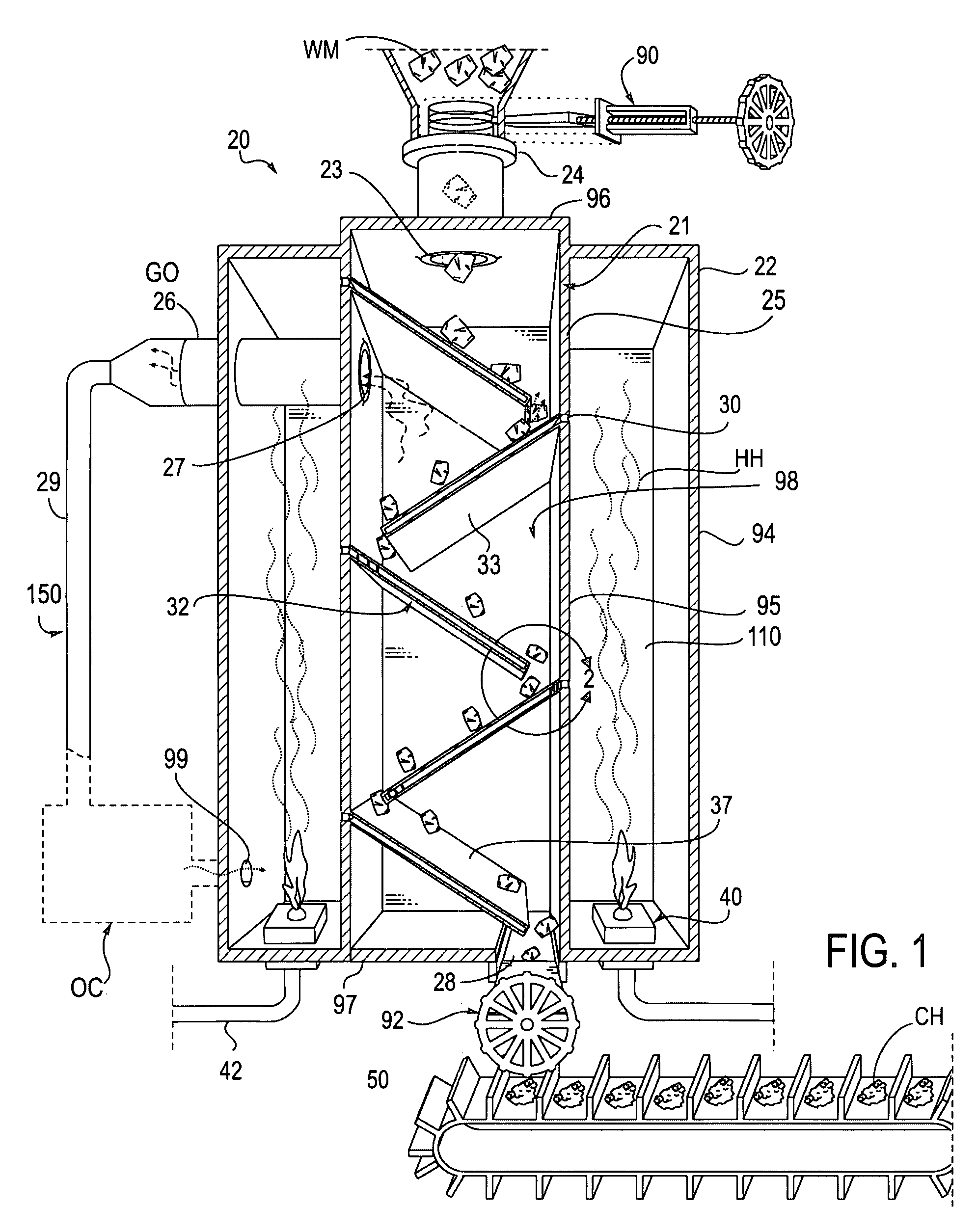
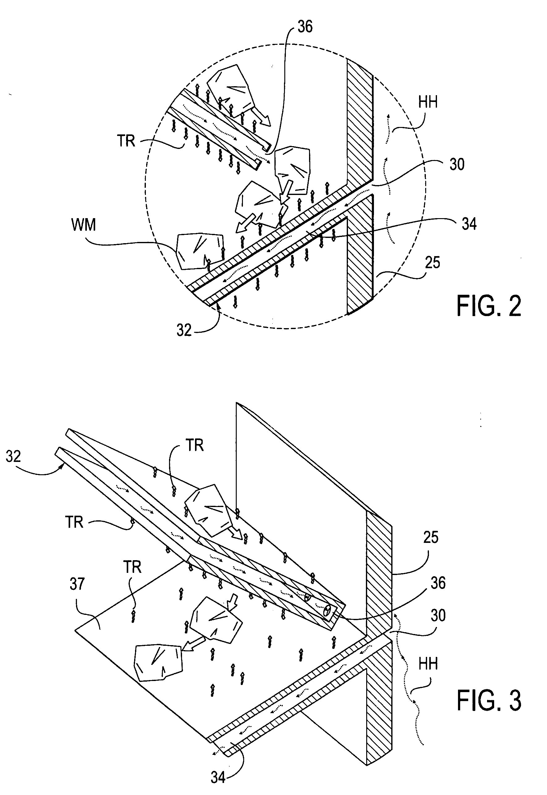
As the waste material freefalls, the heat transfer plates obstruct the material path causing the material to transfer from one plate to the next.

Method used


Image

  • Freefall pyrolytic oven
  • Freefall pyrolytic oven
  • Freefall pyrolytic oven

Examples


third embodiment

[0037]Those ordinary skill in the art will also appreciate that the oven 20 is may be modified to manipulate the retention time of material freefalling through the reaction vessel. In a third embodiment, referring to FIGS. 5-8, an oven 20 is similar to the oven shown in FIG. 1 except that the heat transfer plates 60 are mounted adjustably hinged to the reaction vessel 21 rear wall 65 to variably tilt downward depending on the thermal conversion requirments of the particular waste material being charred. The heat transfer plates 60 are once again typically flat, rectangular hollow plates with solid top 75, bottom 76, front side 73, and rear side 77 surfaces, and made from a high heat conductive and resilient material. In this embodiment, the plates 60 include openings 64 positioned typically on the plate end tilted downward and further include a hinge bolt 62 mounted intermediately along the length of the heat transfer plate 62 through bores 69 located on the forward facing wall 73 a...

fourth embodiment

[0041]A skilled artisan will also recognize that the workman may require a convenient means to install and remove plates as necessary to adjust the material fall path. For these instances, in a fourth embodiment, an oven 20 may be designed to slide heat transfer plates 80 in from the exterior through a removable surface 94 of the heating shell 22 and removable reaction vessel rear wall 98 or front reaction vessel wall (not shown) (FIG. 9). This embodiment is similar to the embodiment shown in FIG. 1 except that heat transfer plate 80 may be slid into a mounted position through slots 72 located in the side walls 25. The heat transfer plate 80 is similar to the heat transfer plates 32 and shown in FIG. 1 also incorporating solid top, bottom and side surfaces with a hollow interior and openings 82 on each plate end. The slots 72 incorporate thermal ports 74 that are aligned with thermal intake ports 82 on plates 80. Slot caps 70 are designed to cover slots 72 not supporting a heat tran...


PUM


Abstract

A pyrolysis oven configured for vertical conveyance of material for incineration. The oven makes use of gravity and multiple plates to control the movement of material through the oven chamber. The plates and oven interior are heated in a low oxygen, pressurized environment to effect the decomposition of material as it freefalls down the chamber and makes contact with heated plates. The configuration and angle of declination of plates determines the freefall rate and retention time within the incinerating environment. The decomposition produces char and gas resultants, each of which are carried off through separate exits configured in the oven. The oven may be used as part of a waste management system in connection with a thermal oxidation chamber for the treatment of volatile organic compound gases that are a by-product of the pyrolytic process.

Description

BACKGROUND OF THE INVENTION[0001]1. Field of the Invention[0002]This invention relates to the field of industrial waste disposal ovens.[0003]2. Description of the Prior Art[0004]As the population increases, the necessity for developing waste management techniques increases in parallel. One dilemma facing modern day waste management facilities is the need to efficiently dispose of solid materials while simultaneously protecting the environment from the harmful by-products of the disposal process. This dilemma is exacerbated by the fact that many materials disposed of by the consuming public are not biodegradable and when submitted to waste managers, may not be simply buried and left for future generations to deal with. As history has shown, burying of non-biodegradable stockpiles does not prevent them or their byproducts from resurfacing and forming toxic waste pools and fumes at some point in the future.[0005]A common disposal alternative to burying materials is incineration. One fo...

Claims


Application Information

Patent Timeline
Patent Type & Authority Applications(United States)
IPC IPC(8): F23M5/00F23G5/00
CPCF23G5/027F23G5/24F23G5/38F23G2201/303C10G1/10F23G2205/18F23G2206/10C10B47/16C10B53/07F23G2205/16Y02P20/143
Inventor GEHRING, MICHAEL W.SWEET, WILLIAM
Owner SIMEKEN
Why Eureka
Try Eureka