Fixing frame for a solar energy module

a solar energy module and fixing frame technology, applied in the direction of heat collector mounting/support, pv power plants, light and heating equipment, etc., can solve the problem of supporting board breaking at welding points, and achieve the effect of high strength, high force resistance, and efficient resistance to external forces

Inactive Publication Date: 2008-09-18
JIN HSIN HO MOLD ENTERPRISE
View PDF7 Cites 15 Cited by
  • Summary
  • Abstract
  • Description
  • Claims
  • Application Information

AI Technical Summary

Benefits of technology

[0008]The primary object of the present invention is a fixing frame for a solar energy module, particularly for an aluminum alloy solar energy module, comprising: a frame body having inserting grooves for a supporting board and a locking chute for a solar panel wherein the locking chute contains the locking flanges. An I-shaped supporting board is installed into the inserting grooves o

Problems solved by technology

1. Poor stability: The solar panel is fixed in the U-shape chute, and therefore there a minor interstice exists between the panel and the chute, resulting in instability.
2. Poor force resistance: The supporting board is fix

Method used


Image

  • Fixing frame for a solar energy module
  • Fixing frame for a solar energy module
  • Fixing frame for a solar energy module

Examples


Embodiment Construction

[0016]While this invention is capable of embodiment in many different forms, shown in the drawings and herein described in detail is the preferred embodiment of the invention. The preferred embodiment is disclosed with the understanding that the present description is but one example of the principles of the invention and is not intended to limit the broad aspects of the invention to the single embodiment illustrated.

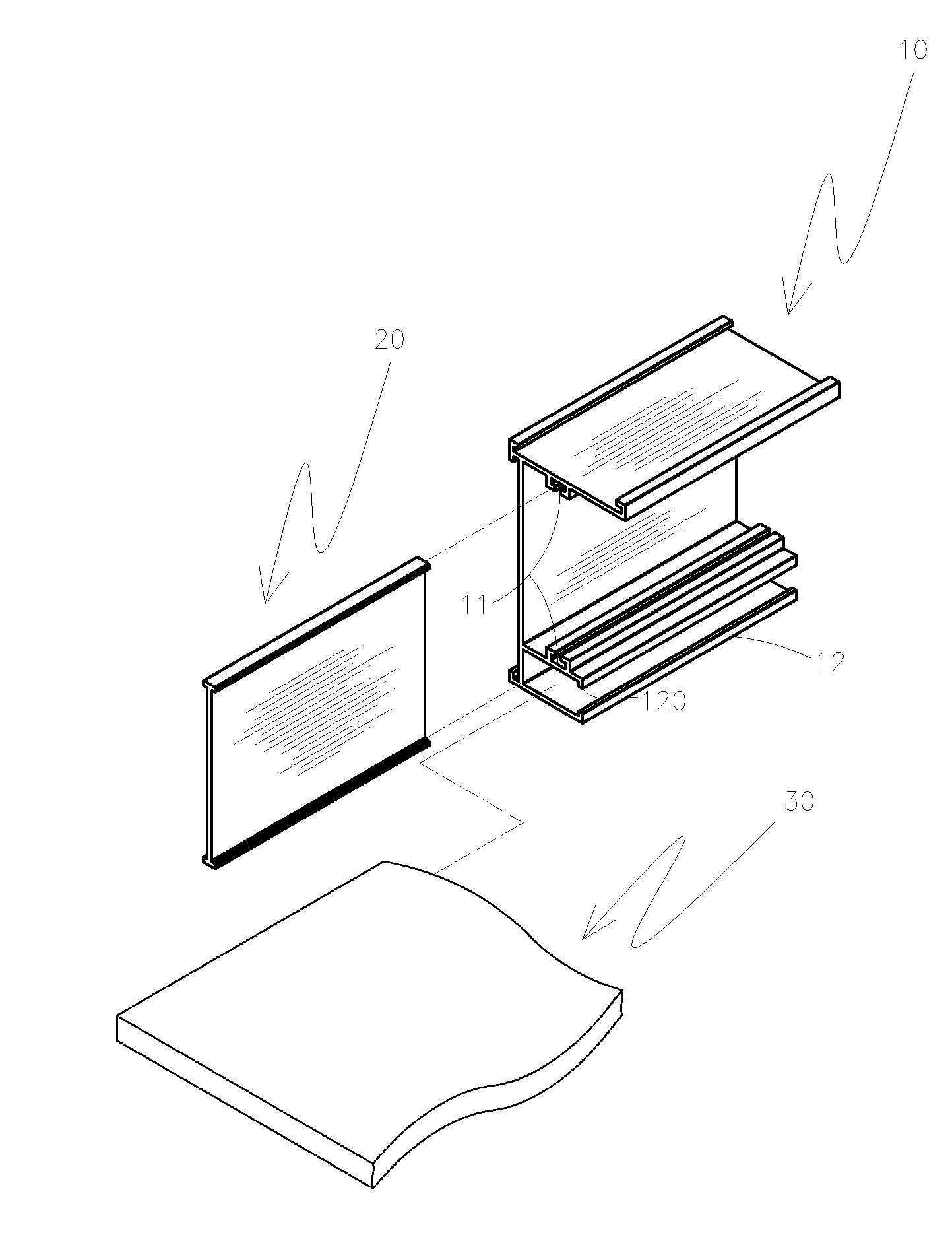
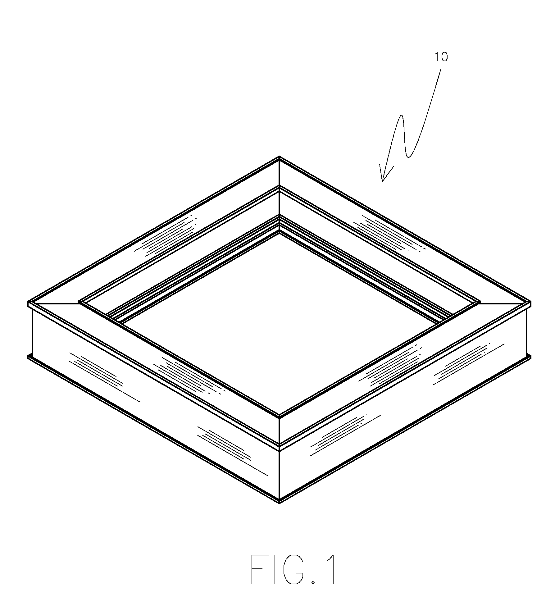
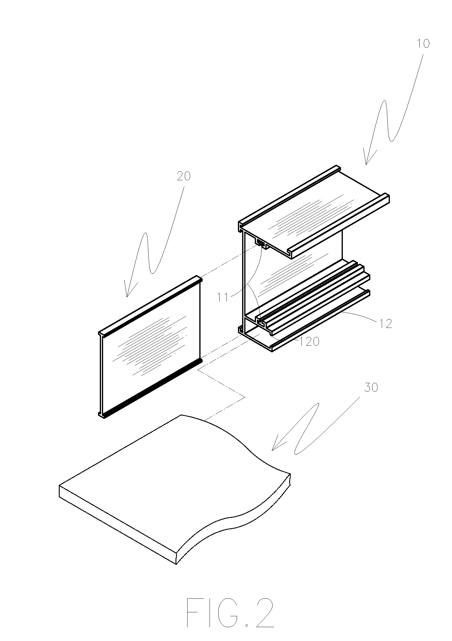
[0017]FIGS. 1 to 3 are perspective, segmented perspective and sectional views schematically showing a fixing frame for a solar energy module of the present invention.

[0018]The frame comprises:

[0019]a frame body 10 having inserting grooves 11 and a locking chute 12, wherein the locking chute 12 contains the locking flanges 120;

[0020]an I-shaped supporting board 20 that is installed by sliding into the inserting grooves 11 of the frame body 10; and

[0021]the frame body 10 and the I-shaped supporting board 20 are made of a high-strength aluminum alloy (aluminum alloy design...


PUM


Abstract

A fixing frame for a solar energy module includes a frame body having inserting grooves for a supporting board and a locking chute for a solar panel, wherein the locking chute contains locking flanges. An I-shaped supporting board is installed into the inserting grooves of the frame body so that it can efficiently resist external forces. During assembly, the solar panel is inserted into the locking chute of the frame body and its top edge and bottom edge are secured by the locking flanges of the chute to ensure stability and high force resistance.

Description

BACKGROUND OF THE INVENTION[0001]1. Field of the Invention[0002]The present invention relates to a fixing frame for a solar energy module. More particularly, the present invention relates to a frame that securely holds a solar panel.[0003]2. Description of Related Art[0004]A conventional fixing frame for a solar module as shown in FIG. 5 and FIG. 6 comprises a frame 50 having a supporting board 51 welded into place; a U-shaped chute 52 is located in the lower portion of the frame 50 and allows a solar panel 30 to be inserted into the chute 52 and fixed in the chute 52. Although the aforesaid frame accomplishes the function of fixing the solar module, it still has some improvable defects, such as:[0005]1. Poor stability: The solar panel is fixed in the U-shape chute, and therefore there a minor interstice exists between the panel and the chute, resulting in instability.[0006]2. Poor force resistance: The supporting board is fixed into the frame via a welding method, and thus when the...

Claims


Application Information

Patent Timeline
IPC IPC(8): E04D13/18
CPCF24J2/5211F24J2002/4656H02S20/00Y02E10/47Y02E10/50F24J2002/5226F24S25/20F24S2025/807F24S2080/09H02S30/10
Inventor LEE, CHANG CHI
Owner JIN HSIN HO MOLD ENTERPRISE
Why Eureka
Try Eureka