Staple Cartridge and Staple Leg Chip Processing Apparatus

a technology of chip processing and staple cartridges, which is applied in the field of staplers, can solve the problems of bringing about an operational failure, large amount of chips generated, and installation of the containing vessel

Active Publication Date: 2008-09-18
MAX CO LTD
View PDF12 Cites 6 Cited by
  • Summary
  • Abstract
  • Description
  • Claims
  • Application Information

AI Technical Summary

Benefits of technology

[0005]One or more embodiments of the invention provide a chip processing apparatus of a staple leg with no need of forming a volume of a containing portion for

Problems solved by technology

According to the stapler which cuts the leading end portion of the staple leg by the cutter unit, by scattering the chip of the staple leg cut by the cutter unit, there is a concern of posing a problem of bringing about an operational failure by being caught in an operating mechanism of a drive gear or a link or the like in the stapler or a printer or

Method used


Image

  • Staple Cartridge and Staple Leg Chip Processing Apparatus
  • Staple Cartridge and Staple Leg Chip Processing Apparatus
  • Staple Cartridge and Staple Leg Chip Processing Apparatus

Examples


embodiment 1

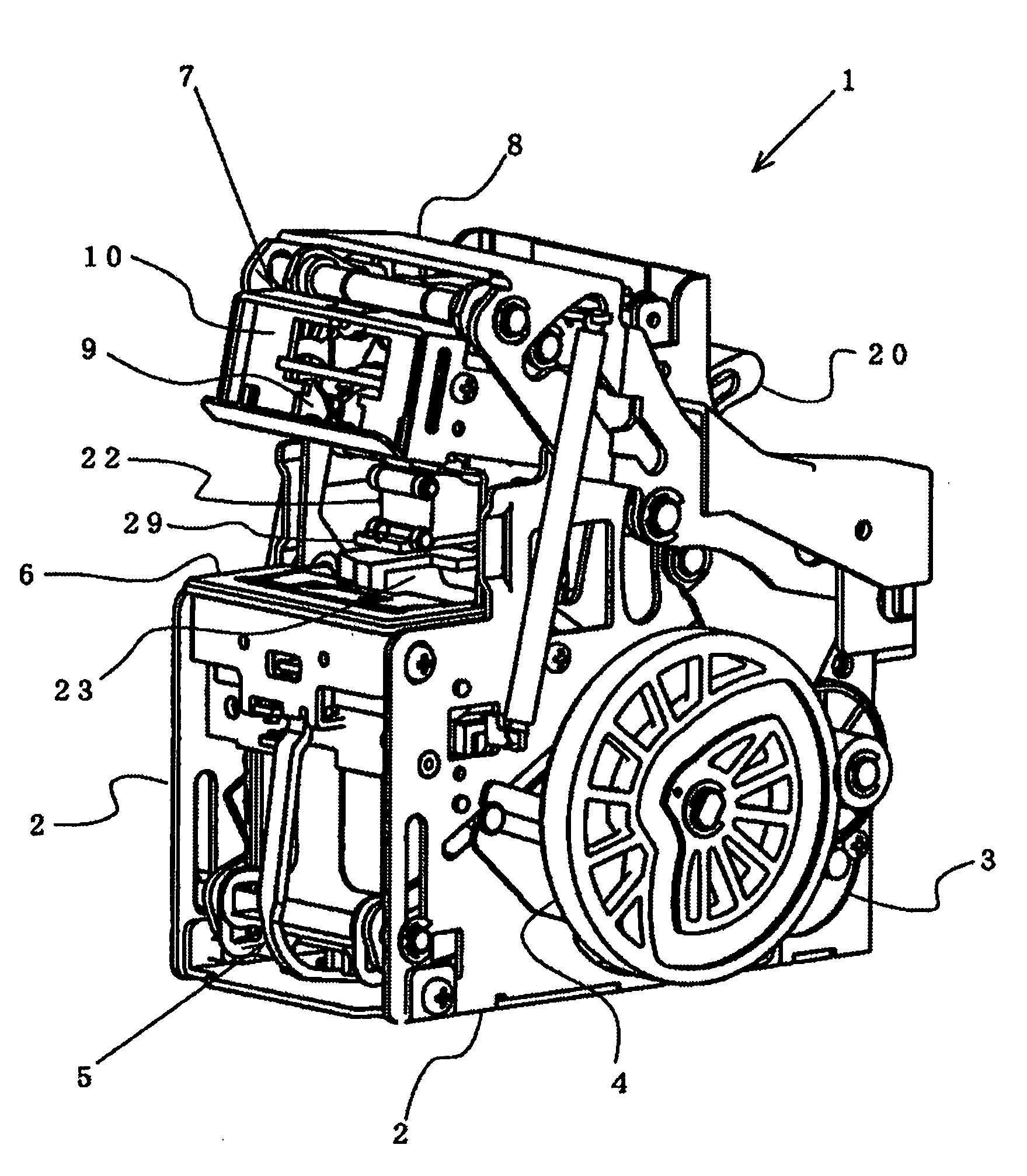
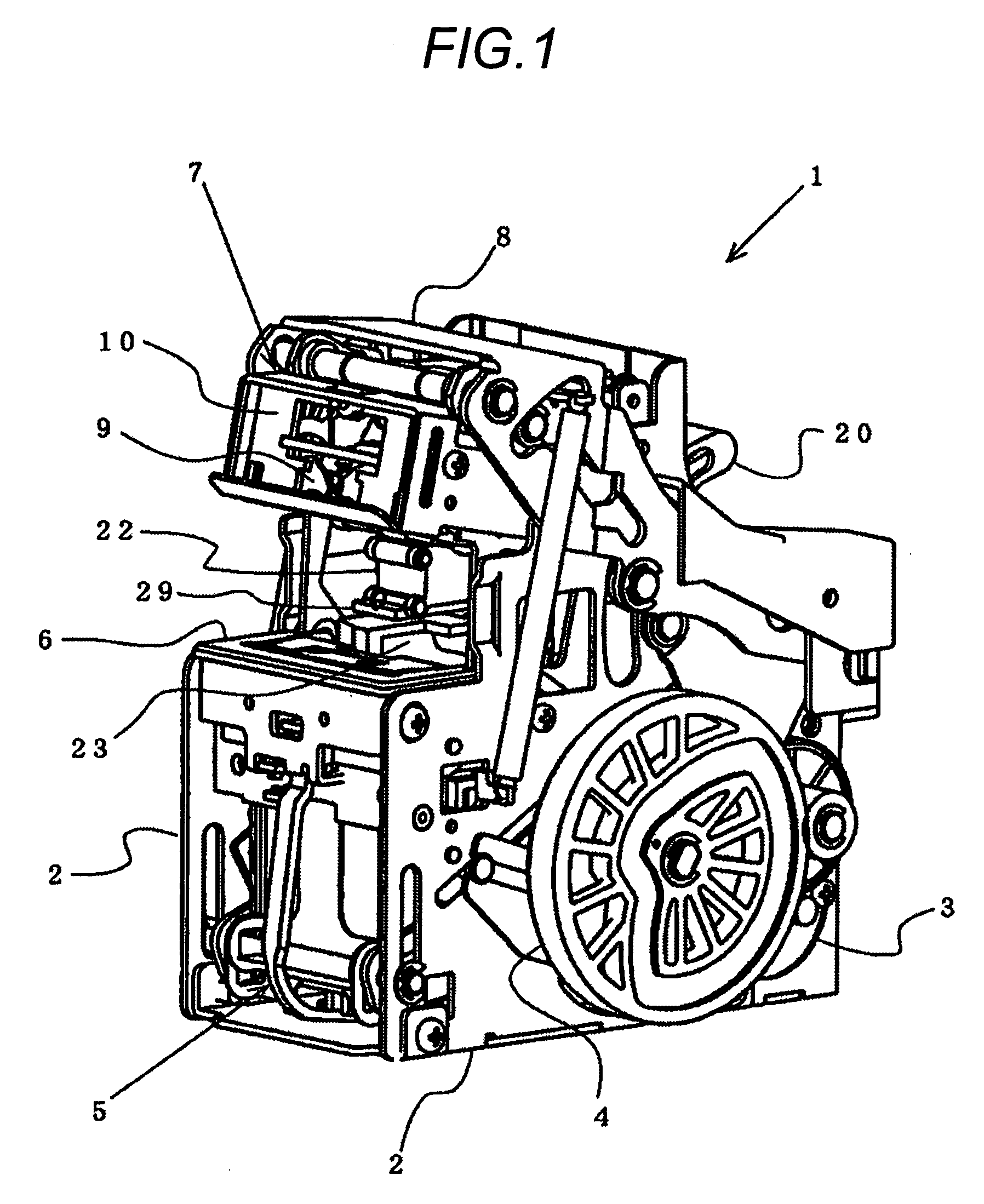
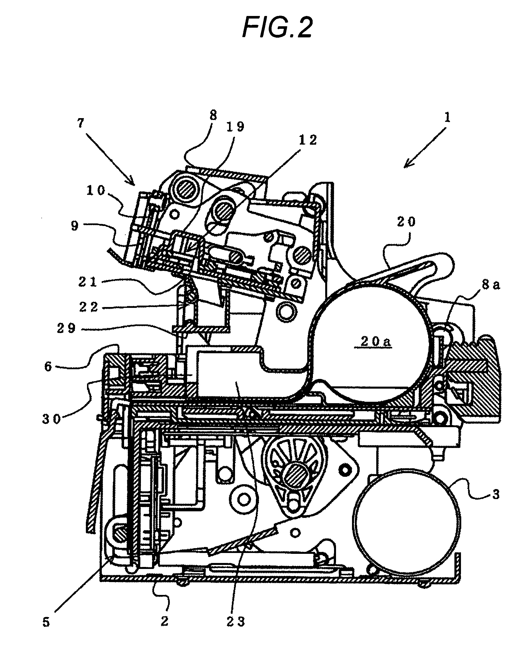
[0032]FIG. 1 and FIG. 2 show a stapler 1 embodying a chip processing apparatus of a staple leg. The stapler 1 of the embodiment is a built-in type stapler for binding a plurality of sheets of paper after printed or copied or the like in a printer or a copier or a finisher or the like. In a machine frame 2 forming an outer shell of the stapler 1, an electric motor 3 is contained. A drive cam 4 driven to rotate by the electric motor 3 is arranged on a side face of the machine frame 2. A lower portion of the machine frame 2 is formed with a strike mechanism portion 5 driven by the drive cam 4 for striking out a staple formed in a U-shape to sheets. Further, an upper face of the machine frame 2 is formed with a table 6 for mounting sheets. The staple is struck from a lower face side of the table 6 to sheets to be bound (sheets) arranged on the table 6 by the strike mechanism portion 5.

[0033]An upper portion of the machine frame 2 is formed with a clincher mechanism portion 7 for bending...


PUM

PropertyMeasurementUnit
Shapeaaaaaaaaaa

Abstract

A stapler 1 is provided with a cutter unit 12 for cutting a leading end portion of a staple leg projected to a back face side of sheets. A staple cartridge 20 containing a number of staples is formed with a chip containing portion 23 for containing a chip of the staple leg. The chip of the staple leg cut by the cutter unit 12 is guided into the chip containing portion 23 of the staple cartridge 20 by a chute 22 formed on the cutter unit 12. The chip of the staple leg is collected in the staple cartridge 20.

Description

TECHNICAL FIELD[0001]The present invention relates to a stapler including a cutter unit for cutting a leading end portion of a staple leg struck out by a strike mechanism and penetrated through sheets to be bound in accordance with a thickness of the sheets to be bound (sheets), particularly relates to a staple cartridge and a processing apparatus of a staple leg chip for preventing a chip of the staple leg cut by the cutter unit from being scattered in the stapler.BACKGROUND ART[0002]In a stapler which is built into a printer or a copier or a finisher or the like for binding a plurality of sheets of paper after printed or copied or the like, there is a stapler which cuts a leading end portion of a staple leg penetrated through the sheets by a cutter unit. Thereby, thin sheets through thick sheets are capable of being bound by a stable shape by making a length of the staple leg projected from the sheets constant. The cutter unit is constituted by a fixed cutter and a movable cutter ...

Claims


Application Information

Patent Timeline
IPC IPC(8): B27F7/19B25C5/02
CPCB27F7/38B27F7/21Y10S83/923Y10T83/222Y10T83/9447
Inventor KISHI, KAZUHIKOSHIMIZU, TOSHIOHAKOZAKI, KATSUYAHIGUCHI, KAZUO
Owner MAX CO LTD
Why Eureka
Try Eureka