

High-Performance Low-Noise Aircraft Exhaust Systems and Methods
- Summary
- Abstract
- Description
- Claims
- Application Information
AI Technical Summary
Benefits of technology
Problems solved by technology
Method used
Image

Examples
embodiment 0
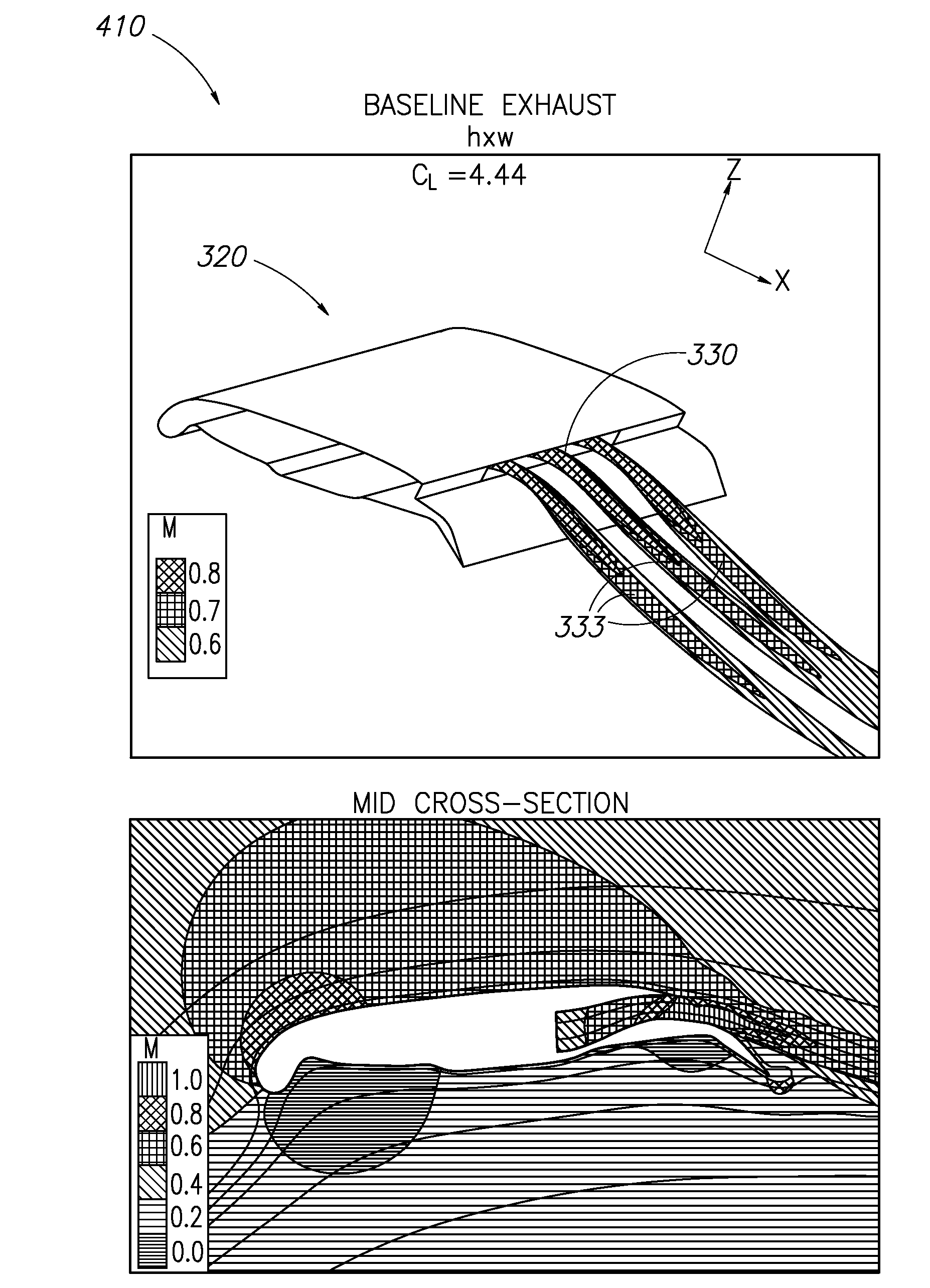
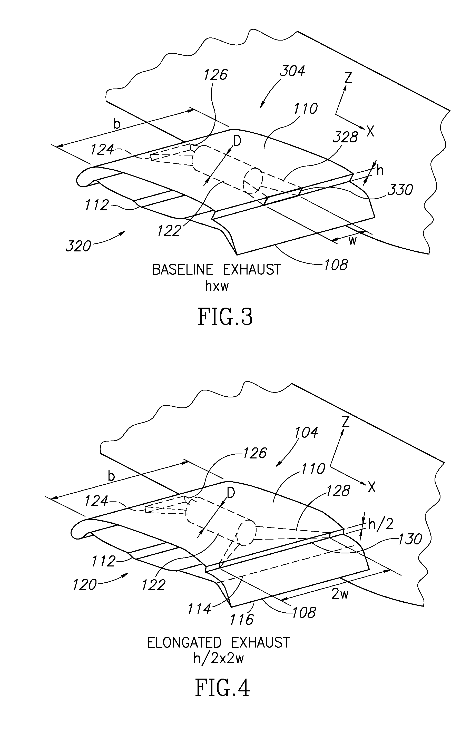
[0036]It will be appreciated that the shape of the exhaust aperture 330 may vary (or may remain constant) depending upon the various operating conditions of the engine 122 throughout the operating regime of the aircraft 100. As shown in FIG. 3, however, at a particular design operating condition of the engine 122 (e.g. maximum power setting, takeoff power setting, etc.), the exhaust aperture 330 has a height h and a width w. More specifically, the exhaust aperture 330 at the design operating condition may provide an exit area (h×w) that is closely comparable to the exit area of prior art exhaust apertures, however, an aspect ratio AR (defined as width over height w / h) of the inventive exhaust aperture 330 is significantly larger than the aspect ratio of prior art exhaust apertures, as described more fully below with respect to FIG. 17. For example, the maximum value of the aspect ratio AR of the exhaust aperture in the prior art is 3.6, while the exhaust aperture 330 of the baseline...
embodiment 00
[0038]More specifically, at the same design operating condition (e.g. maximum power setting, takeoff power setting, etc.), the exhaust aperture 130 may have a reduced height of h / 2 and an elongated width of 2w. Thus, the exhaust aperture 130 provides the same exit area as the baseline exhaust aperture 330, but the aspect ratio AR of the elongated exhaust aperture 130 (4w / h) is approximately 24 (see embodiment 00 of FIG. 17), or approximately 6.7 times greater than the aspect ratio AR of the baseline exhaust aperture 330 (w / h) at the same design operating condition of the engine 122. In alternate embodiments, the aspect ratio AR of exhaust apertures in accordance with the teachings of the present disclosure may be greater than or less than that of the particular configurations shown in FIGS. 3 and 4, as described more fully below with respect to FIG. 17.
[0039]In some embodiments, a set of actuators may be used to move an ensemble of interlocking leaves which collectively form the exh...
second embodiment
[0059]Similarly, in FIG. 20 the exhaust system 560 corresponding to the table 500 (FIG. 17) includes the engines 512 as in the prior art exhaust system 520. A plurality of exhaust ducts 562 extend rearwardly from the engines 512 to an exhaust aperture 564 having an aspect ratio AR of 33, which is approximately 9 times greater than the aspect ratio AR of the prior art exhaust aperture 524.
PUM
 Abstract
Description
Claims
Application Information