Eureka AIR delivers breakthrough ideas for toughest innovation challenges, trusted by R&D personnel around the world.

Semiconductor package and fabricating method thereof

a technology of semiconductors and chip packages, applied in the direction of semiconductor devices, semiconductor/solid-state device details, electrical apparatus, etc., can solve the problems of large stress localized at the solder ball, the failure the inability to meet the requirements of reliable interconnect systems, etc., to achieve the effect of restoring the resistance characteristics of the connection, reducing the propagation of cracks, and improving reliability

Inactive Publication Date: 2008-09-18
SAMSUNG ELECTRONICS CO LTD
View PDF5 Cites 17 Cited by
  • Summary
  • Abstract
  • Description
  • Claims
  • Application Information

AI Technical Summary

Benefits of technology

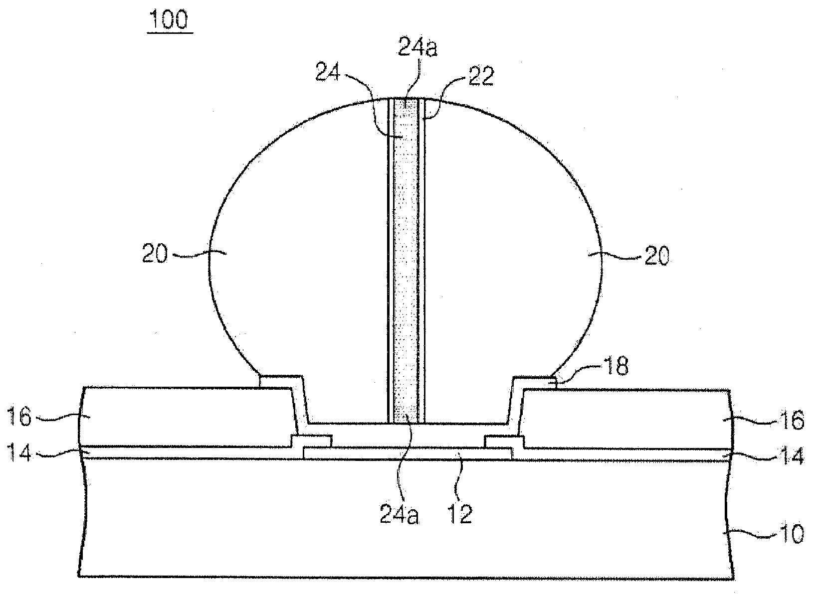
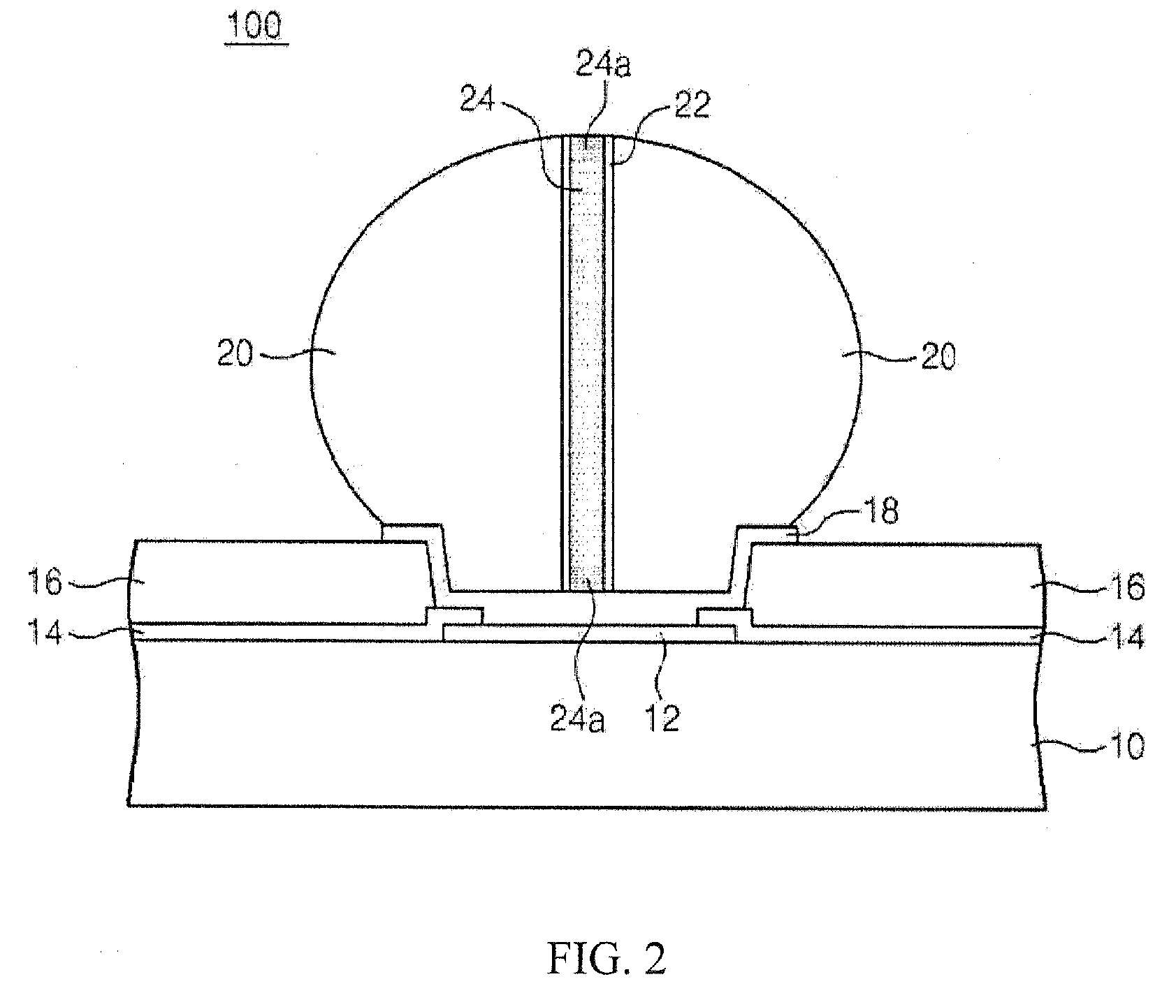
[0010]Embodiments of the present invention provide a semiconductor device including a substrate, an electrode pad disposed on the substrate, an external terminal disposed on the electrode pad, a container extended from the electrode pad into the external terminal, and a conductive liquid disposed inside the container. The conductive liquid solidifies when exposed to air. When a crack forms in the external terminal, the container suppresses propagation of the crack. Further, if the crack breaches the container, the conductive liquid fills the crack and may solidify in the crack if exposed to air. A method of forming a semiconductor device including a container having a conductive liquid is also provided.
[0011]According to embodiments of the invention, crack propagation within the external terminal is suppressed by the container. Further, if the crack breaches the container, the conductive liquid from the container fills the crack, restoring the resistance characteristics of the connection. Therefore, connections between chip packages and PCBs according to embodiments of the present invention have improved reliability over conventional methods.

Problems solved by technology

As the microelectronics industry continues to develop increasingly complex devices with extremely small feature sizes, creating reliable interconnect systems becomes a significant challenge.
During these temperature cycles, a mismatch between the coefficient of thermal expansion (CTE) of the chip package substrate and the CTE of the PCB causes stress to be localized at the solder balls.
Thus, large differences in CTE and large temperature variations lead to large stress localized at the solder balls.
This localized stress can lead to cracks in the solder balls.
Even small cracks can lead to an increase in the resistance of the solder ball connection, which may adversely affect the operational reliability of the resulting device.
However, if the cracks are allowed to propagate through the solder ball, by repeated temperature cycles for instance, the solder ball connection may completely fail, causing an open connection between the chip package and the PCB.
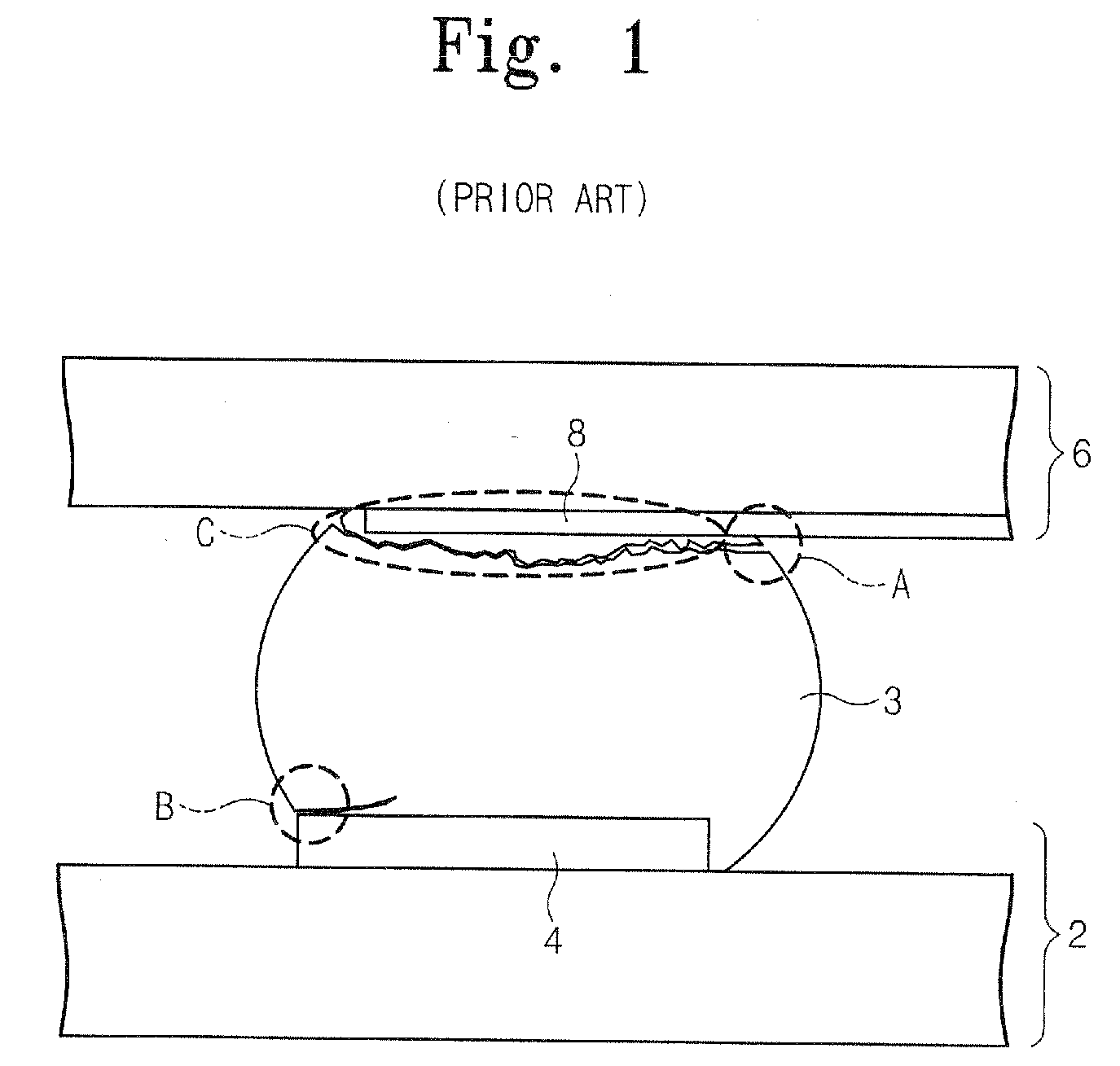
However, cracks may form at center portions of the solder ball 3 as well.
The cracks shown in details A, B, and C can lead to degradation of the solder connection, reduced reliability of the solder connection, and / or complete failure of the solder connection, each of which can lead to a device failure.
However, although the structure of Oh may reduce crack propagation to prevent an open connection, it does not remedy the increase of resistance due to the cracks in the solder bump.
Further, if the crack breaches the container, the conductive liquid fills the crack and may solidify in the crack if exposed to air.

Method used


Image

  • Semiconductor package and fabricating method thereof
  • Semiconductor package and fabricating method thereof
  • Semiconductor package and fabricating method thereof

Examples


Embodiment Construction

[0024]The invention is described more fully hereinafter with reference to the accompanying drawings, in which various embodiments of the invention are shown. This invention may, however, be embodied in many different forms and should not be construed as limited to the particular embodiments set forth herein. Rather, these embodiments are provided so that this disclosure will be thorough and complete, and will convey the scope of the invention to those skilled in the art. In the drawings, the size and relative sizes of layers and regions may be exaggerated for clarity.

[0025]It will be understood that when an element or layer is referred to as being “on,”“connected to” or “coupled to” another element or layer, it can be directly on, connected or coupled to the other element or layer or intervening elements or layers may be present. In contrast, when an element is referred to as being “directly on,”“directly connected to” or “directly coupled to” another element or layer, there are no ...


PUM


Abstract

Provided is a semiconductor device including a substrate, an electrode pad disposed on the substrate, an external terminal disposed on the electrode pad, a container extended from the electrode pad into the external terminal, and a conductive liquid disposed inside the container. The conductive liquid solidifies when exposed to air. When a crack forms in the external terminal, the container suppresses propagation of the crack. Further, if the crack breaches the container, the conductive liquid fills the crack, thereby minimizing further crack propagation and recovering the resistance characteristics of the external terminal prior to the crack formation. A method of forming a semiconductor device including a container having a conductive liquid is also provided.

Description

CROSS-REFERENCE TO RELATED APPLICATIONS[0001]This application claims priority under 35 USC § 119 to Korean Patent Application No. 2006-097307, filed on Oct. 2, 2006, and No. 2006-121657, filed on Dec. 4, 2006, the contents of which are herein incorporated by reference in their entirety.BACKGROUND[0002]1. Technical Field[0003]The disclosure relates to a semiconductor chip package and a system including the package. More particularly, the disclosure relates to a semiconductor chip package and a system including the package that is electrically and physically connected to a circuit board via an external terminal.[0004]2. Description of the Related Art[0005]As the microelectronics industry continues to develop increasingly complex devices with extremely small feature sizes, creating reliable interconnect systems becomes a significant challenge. A common method of attaching a chip package to a composite printed circuit board (PCB) is with a ball grid array (BGA) configuration. In this co...

Claims


Application Information

Patent Timeline
IPC IPC(8): H01L23/488H01L21/44
CPCH01L24/11H01L2224/13078H01L24/16H01L24/81H01L2224/1132H01L2224/1184H01L2224/13099H01L2224/16H01L2224/81136H01L2224/81801H01L2924/01013H01L2924/01015H01L2924/01029H01L2924/01033H01L2924/01078H01L2924/01079H01L2924/01082H01L2924/01005H01L2924/01006H01L2924/01024H01L2924/014H01L2224/05557H01L2224/81141H01L2224/0401H01L2224/13076H01L24/12H01L24/05H01L2224/05144H01L2224/05147H01L2224/05155H01L2224/05171H01L2224/05644H01L2224/05647H01L2224/05655H01L2224/05671H01L2224/131H01L2924/00H01L2924/00014H01L2924/013H01L2224/13194
Inventor LEE, IN
Owner SAMSUNG ELECTRONICS CO LTD
Why Eureka
Eureka Blog
Learn More