Lighting system with power factor correction control data determined from a phase modulated signal

a phase modulated signal and control data technology, applied in the field of electrical and lighting, can solve the problems of ineffective power use, inconvenient operation, and ripple during phase delays, and achieve the effect of decreasing the effective resistan

Active Publication Date: 2008-09-18
SIGNIFY HLDG BV
View PDF102 Cites 313 Cited by
  • Summary
  • Abstract
  • Description
  • Claims
  • Application Information

AI Technical Summary

Benefits of technology

[0029]In a further embodiment of the present invention, a light emitting diode (LED) lighting system includes a power factor correction (PFC) controller to receive a signal indicating a dimming level and to generate a PFC switch control signal to cause a PFC LED driver circuit to respond to the dimming level indicated by the signal without decreasing an effective resistance of the PFC load driver circuit, as perceived by a voltage source of the PFC load driver circuit, as the dimming level indicated by the signal increa

Problems solved by technology

Decreasing the effective resistance REFF—0 of light source driver circuit 106 when dimming light source 102 represents an inefficient use of power.
Conventional dimmers, such as a triac based dimmer, that are designed for use with inactive loads, such as incandescent light bulbs, often do not perform well when supplying a raw phase modulated signal VΦ—RAW to an active load such as light source dri

Method used


Image

  • Lighting system with power factor correction control data determined from a phase modulated signal
  • Lighting system with power factor correction control data determined from a phase modulated signal
  • Lighting system with power factor correction control data determined from a phase modulated signal

Examples


Embodiment Construction

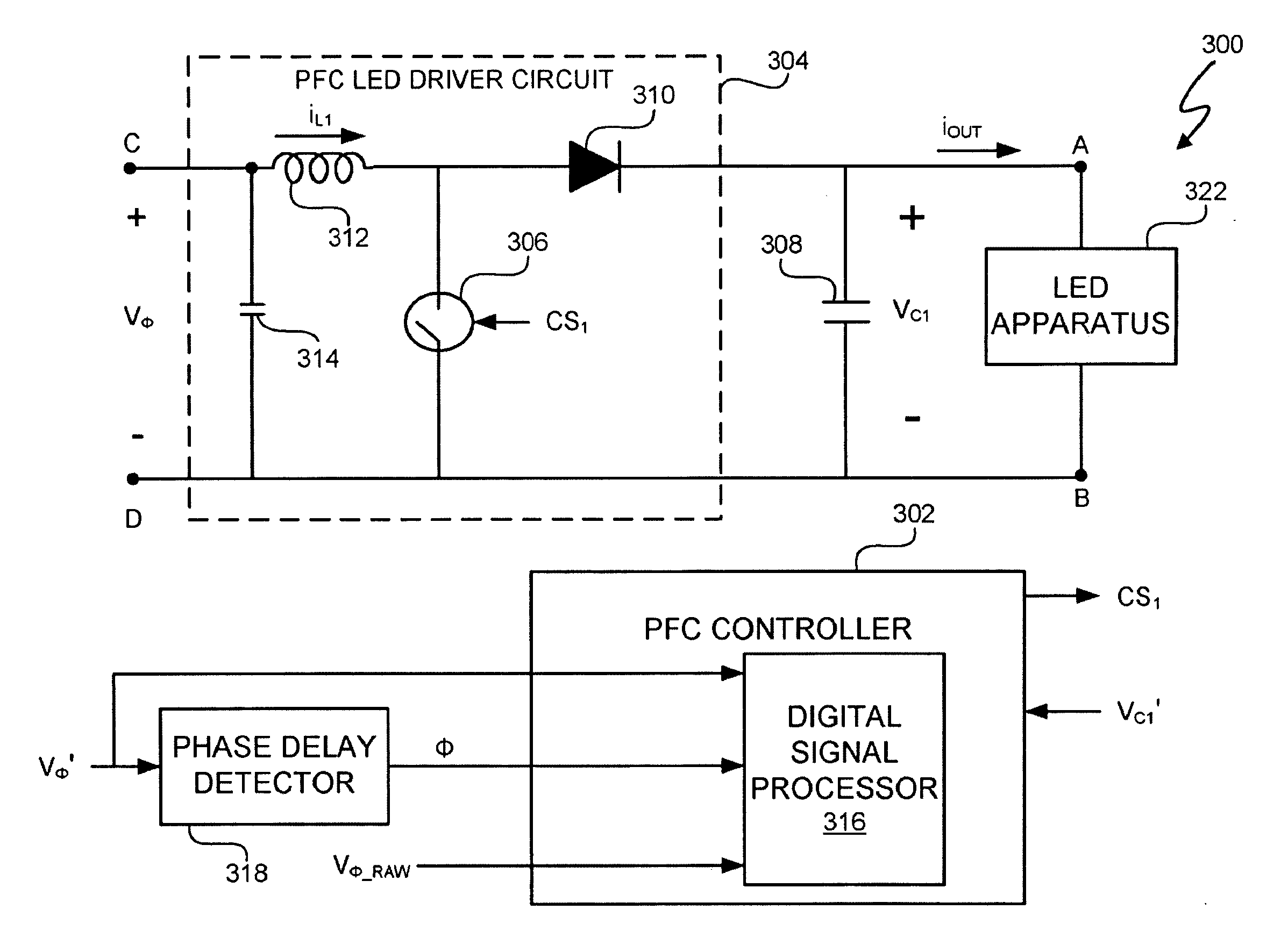
[0048]A light emitting diode (LED) lighting system includes a power factor correction (PFC) controller that determines at least one power factor correction control parameter from phase delays of a phase modulated signal. In at least one embodiment, a peak voltage of the phase modulated signal is a PFC control parameter used by the PFC controller to control power factor correction and generation of a link voltage by a PFC LED driver circuit. The phase delays are related to a peak voltage of the phase modulated signal. Thus, in at least one embodiment, detecting the phase delay in one or more cycles of the phase modulated signal allows the PFC controller to determine the peak voltage of the phase modulated signal.

[0049]The PFC LED driver circuit supplies an output current to drive LED(s) of an LED apparatus. As the dimming level decreases, the PFC controller decreases a duty cycle of a PFC switch in the PFC LED driver circuit to cause the PFC LED driver circuit to decrease the output ...


PUM


Abstract

A light emitting diode (LED) lighting system includes a power factor correction (PFC) controller that determines at least one power factor correction control parameter from phase delays of a phase modulated signal. In at least one embodiment, a peak voltage of the phase modulated signal is a PFC control parameter used bit the PFC controller to control power factor correction and generation of a link voltage by a PFC LED driver circuit. The phase delays are related to a peak voltage of the phase modulated signal. Thus, in at least one embodiment, detecting the phase delay in one or more cycles of the phase modulated signal allows the PFC controller to determine the peak voltage of the phase modulated signal.

Description

CROSS REFERENCE TO RELATED APPLICATIONS[0001]This application claims the benefit under 35 U.S.C. § 119(e) and 37 C.F.R. § 1.78 of U.S. Provisional Application No. 60 / 894,295, filed Mar. 12, 2007 and entitled “Lighting Fixture.” U.S. Provisional Application No. 60 / 894,295 includes exemplary systems and methods and is incorporated by reference in its entirety.[0002]This application claims the benefit under 35 U.S.C. § 119(e) and 37 C.F.R. § 1.78 of U.S. Provisional Application No. 60 / 909,458, entitled “Ballast for Light Emitting Diode Light Sources,” inventor John L. Melanson, Attorney Docket No. 1666-CA-PROV, and filed on Apr. 1, 2007 describes exemplary methods and systems and is incorporated by reference in its entirety.[0003]U.S. patent application Ser. No. ______, entitled “.Ballast for Light Emitting Diode Light Sources,” inventor John L. Melanson, Attorney Docket No. 1666-CA. and filed on Mar. 12, 2008 describes exemplary methods and systems and is incorporated by reference in ...

Claims


Application Information

Patent Timeline
IPC IPC(8): H05B37/02H05B44/00
CPCH05B33/0815Y10S315/04Y02B20/347H05B33/0818H05B45/38H05B45/355Y02B20/30
Inventor MELANSON, JOHN L.
Owner SIGNIFY HLDG BV
Why Eureka
Try Eureka