Liquid Crystal Projector, and Liquid Crystal Panel and Liquid Cooling Apparatus Thereof

a technology of liquid crystal projectors and liquid crystal panels, which is applied in the direction of projectors, color television details, instruments, etc., can solve the problem of not being able to say that they can provide structures

Inactive Publication Date: 2008-09-18
HITACHI LTD
View PDF7 Cites 20 Cited by
  • Summary
  • Abstract
  • Description
  • Claims
  • Application Information

AI Technical Summary

Benefits of technology

[0029]Then, according to the present invention, being accomplished by taking the problems in the conventional arts mentioned above into the consideration thereof, an object thereof is to provide a liquid crystal projector, and further a liquid crystal panel and a liquid cooling apparatus thereof, for it; i.e., in particular, enabling to cool the liquid crystal panels with utilizing the liquid cooling cycle circulating the liquid coolant therein, effectively, and in particular, the difference in density within the liquid coolant passing through the transparent surface of the liquid crystal panel due to the difference in velocity and the difference in temperature, etc., and for that reason, giving such the ill influences upon the picture, hardly, which passes through the liquid crystal panel; thereby obtaining a preferable projection image.

Problems solved by technology

However, with the cooling structures of the liquid crystal panels in the various kinds of projectors, which are proposed in the various conventional arts mentioned above, in particular, it is still impossible to say that they can provide the structures being suitable for cooling those liquid crystal panels, with applying the cooling cycle circulating the liquid coolant therein, effectively, including picture quality of the pictures projected, in case when they are applied into a liquid projector of the method, in particular, synthesizing the lights in three (3) directions obtained from the light source by means of the prism, after passing through the crystal panels for use of three (3) fundamental colors, R, G and B, respectively.

Method used


Image

  • Liquid Crystal Projector, and Liquid Crystal Panel and Liquid Cooling Apparatus Thereof
  • Liquid Crystal Projector, and Liquid Crystal Panel and Liquid Cooling Apparatus Thereof
  • Liquid Crystal Projector, and Liquid Crystal Panel and Liquid Cooling Apparatus Thereof

Examples


embodiment 1

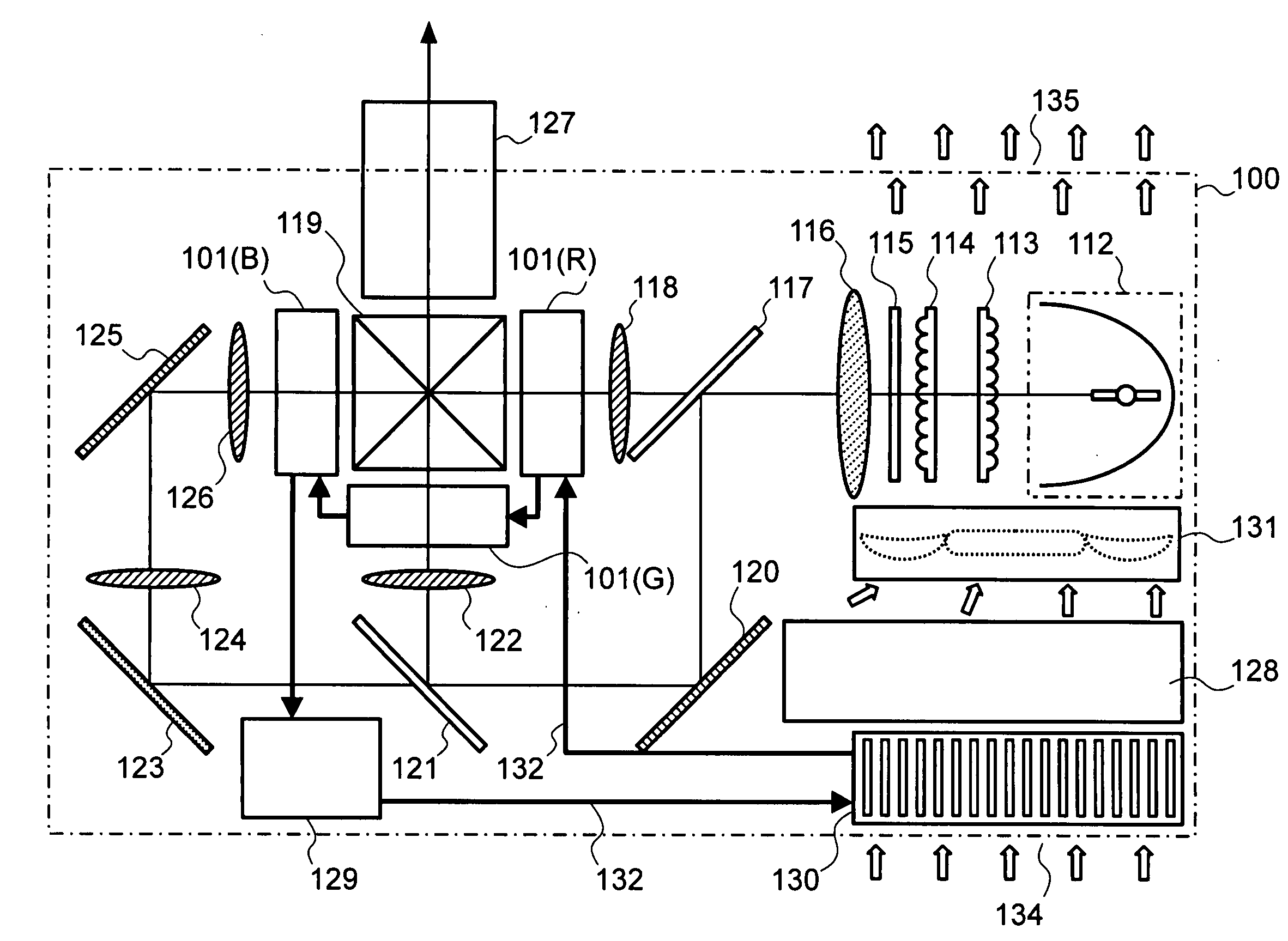
[0055]First of all, FIG. 3 shows an example of the entire structures of a liquid crystal projector, comprising a liquid cooling apparatus for liquid crystal panels therein, according to an embodiment of the present invention. In the figure, a reference numeral 100 depicts a housing of the liquid crystal projector, and also, as is apparent from the figure, within an inside thereof is provided a light irradiation source, such as, a metal halide lamp 112, for example. And, the lights from the light irradiation source 112 are brought into a parallel light by the functions of a first lens array 113, a second lens array 114, a polarization converter element 115 and a condensing lens 116, to be outputted. This parallel light, thereafter, is guided onto a first dichroic mirror 117, and a part thereof, while penetrating through it, is guided onto a liquid crystal panel 101(R) for use of R (red) through a first condenser lens 118, to be modulated therein, and thereafter it reaches to a photos...

embodiment 2

[0078]Next, explanation will be made on the embodiment 2, according to the present invention, by referring to drawings attached herewith. However, in this embodiment 2, the constituent elements common to those, which are illustrated in the above embodiment 1, are also attached with the same reference numerals thereof.

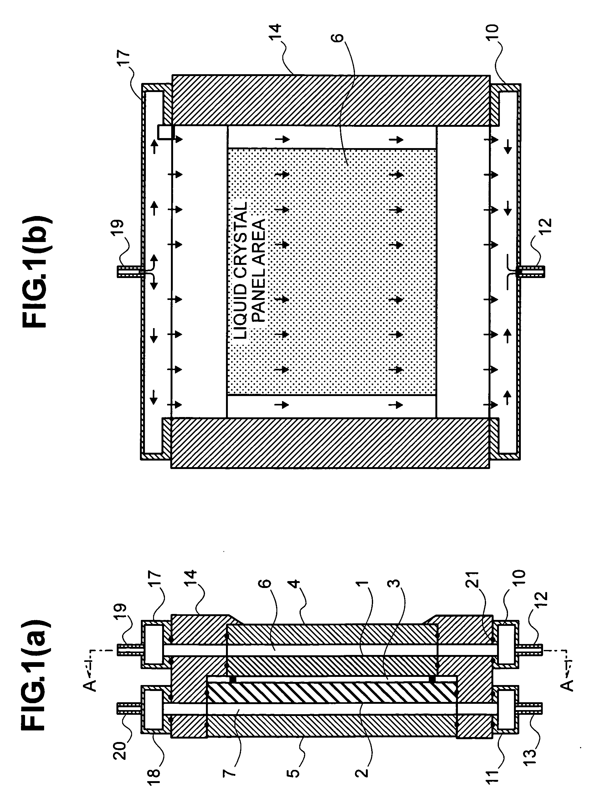
[0079]FIGS. 8(a) and 8(b) show the detailed interior structures of the liquid crystal panel 101, representatively, one of those liquid crystal panels 101(R), 101(G) and 101(B) for R, G and B mentioned above. Firstly, in FIG. 8(a) showing the cross-section of the liquid crystal panel 101, a reference numeral 2 depicts a TFT substrate made of a glass, for example, on the surface of which a large number of transistor driver elements are formed, building up a main constituent element of that liquid crystal panel 101, while an opposite substrate 1 also made of glass is disposed opposing to that liquid crystal panel 101, and a liquid crystal 3 is sealed or enclosed between th...


PUM

PropertyMeasurementUnit
thicknessaaaaaaaaaa
thicknessaaaaaaaaaa
flow resistanceaaaaaaaaaa

Abstract

A liquid crystal projector, a liquid crystal panel, and a liquid cooling apparatus, for obtaining a picture without disturbance due to a liquid coolant passing through a transparent surface of the liquid crystal panel, with achieving cooling effectively with an aid of a liquid cooling cycle, wherein lights from a light source 112 is divided into three (3) parallel light beams,

Description

TECHNICAL FIELD[0001]The present invention relates to a liquid crystal projector for projecting lights from a light source through liquid crystal panels, being called by a “light bulb”, and a liquid crystal panel, as an image on a screen, and it relates to, in particular, the structures of a liquid crystal panel, which is applied within such the liquid crystal projector, and also a liquid cooling apparatus for cooling such the liquid crystal panel through a liquid coolant.BACKGROUND ARTS[0002]In recent years, within field of a projection apparatus for displaying a color image screen, etc., on a personal computer, through enlarged projection thereof (hereinafter, being called simply by a “projector”), for example, an apparatus has been widely put into practical use, resolving or dividing the light obtained from a light source, such as, a metal halide lamp, etc., for example, into three (3) directions, and projecting them on a screen through a projection lens or the like, after modula...

Claims


Application Information

Patent Timeline
Patent Type & Authority Applications(United States)
IPC IPC(8): G02F1/1333
CPCG02F1/133385G03B21/16H05K7/20981H04N9/3197H04N9/3144
Inventor HOSHINO, MASAKAZUMINAMITANI, RINTARONAGANAWA, TAKASHITERAKADO, SHUICHI
Owner HITACHI LTD
Why Eureka
Try Eureka