Apparatus and Method for Appearance Inspection

a technology of appearance inspection and apparatus, applied in the field of apparatus and method for appearance inspection, can solve the problems of increasing the number of components, increasing the cost of apparatus, increasing the size of apparatus, etc., and reducing the reliability, so as to improve the x resolution and reduce the inspection accuracy. , the effect of preventing the decrease of inspection accuracy

Inactive Publication Date: 2008-09-18
PANASONIC CORP
View PDF4 Cites 14 Cited by
  • Summary
  • Abstract
  • Description
  • Claims
  • Application Information

AI Technical Summary

Benefits of technology

[0048]According to the first or fifth mode of the present invention, the mirror surface of the rotating polygon mirror is configured to have the different mirror surface angle which is of an angle formed between the rotation axis and the mirror surface such that the collecting point of the scanning light flux is shifted in the sub-scanning direction in association with the rotation at constant angular speed, the collecting point position forming optical system is configured such that the collecting point is moved in the inspection range in the height direction, the collecting point is moved in the inspection range in the height direction in synchronization with the rotation of the rotating polygon mirror at constant angular speed, and the inspection object is moved in the sub-scanning direction such that the collecting point shifted in the sub-scanning direction is linearly scanned in the height direction of the inspection object. Therefore, during the rotating operation of the rotating polygon mirror, the scanning (X scanning) can be performed in the main scanning direction with respect to the inspection object by one mirror surface, the scanning (Z scanning) can be performed in the height direction with respect to the inspection object by changing the mirror surfaces having the different mirror surface angles in one revolution of the rotating polygon mirror, and the scanning (Y scanning) can be performed in the sub-scanning direction with respect to the inspection object by performing the plural revolutions of the rotating polygon mirror while moving the inspection object in the sub-scanning direction. That is, the Z scanning can be incorporated into the XY scanning mechanism, and the high-speed appearance inspection can be realized with the simple mechanism as described above.
[0049]In the case where the appearance inspection is performed to the inspection object by the first mode of the present invention, the computation unit can perform the stereoscopic appearance inspection of the inspection object by determining the total of (2×2×3=) 12 ...

Problems solved by technology

Therefore, when the XY scanning and the Z scanning are simultaneously realized to achieve the speedup, the number of components i...

Method used


Image

  • Apparatus and Method for Appearance Inspection
  • Apparatus and Method for Appearance Inspection
  • Apparatus and Method for Appearance Inspection

Examples


first embodiment

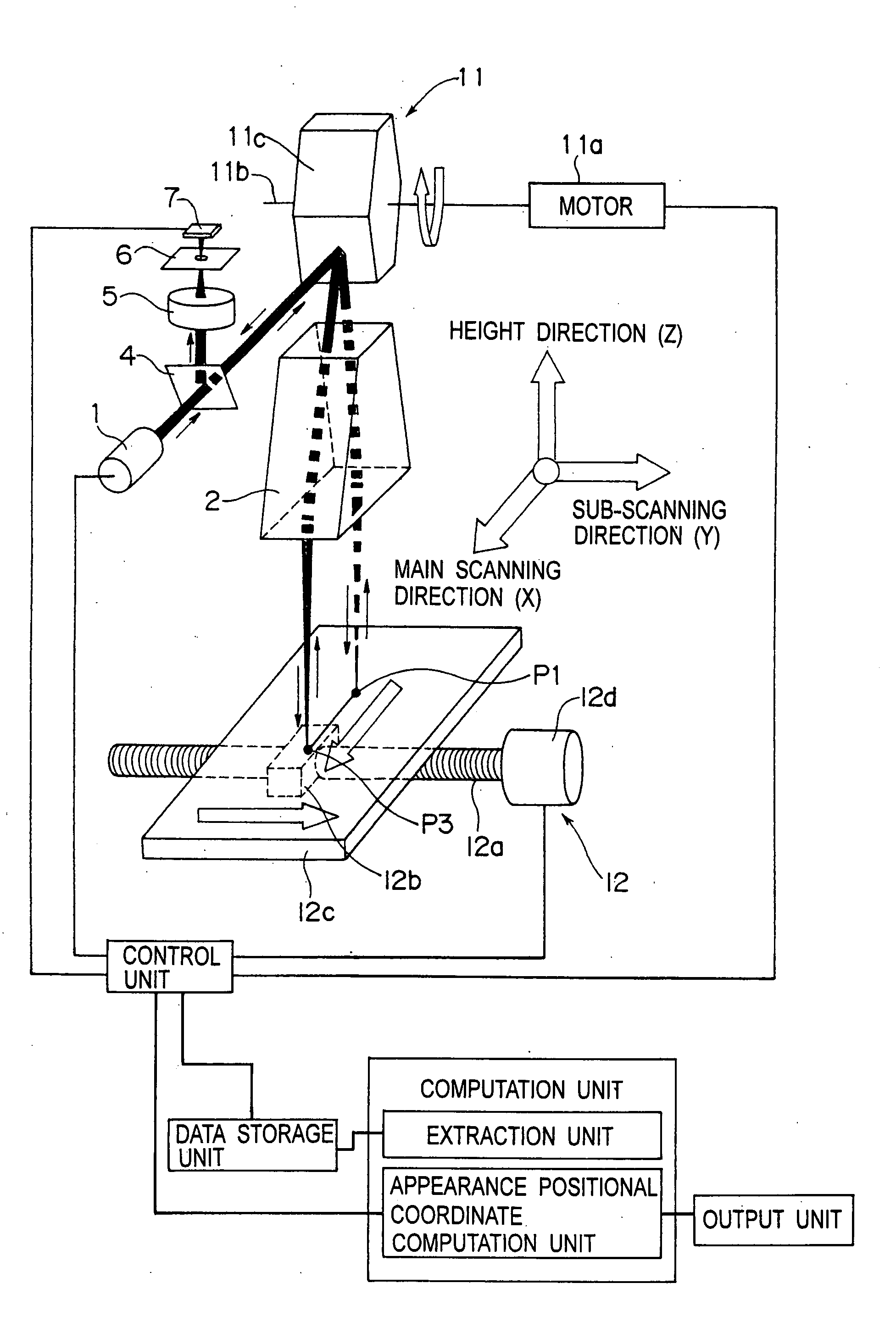
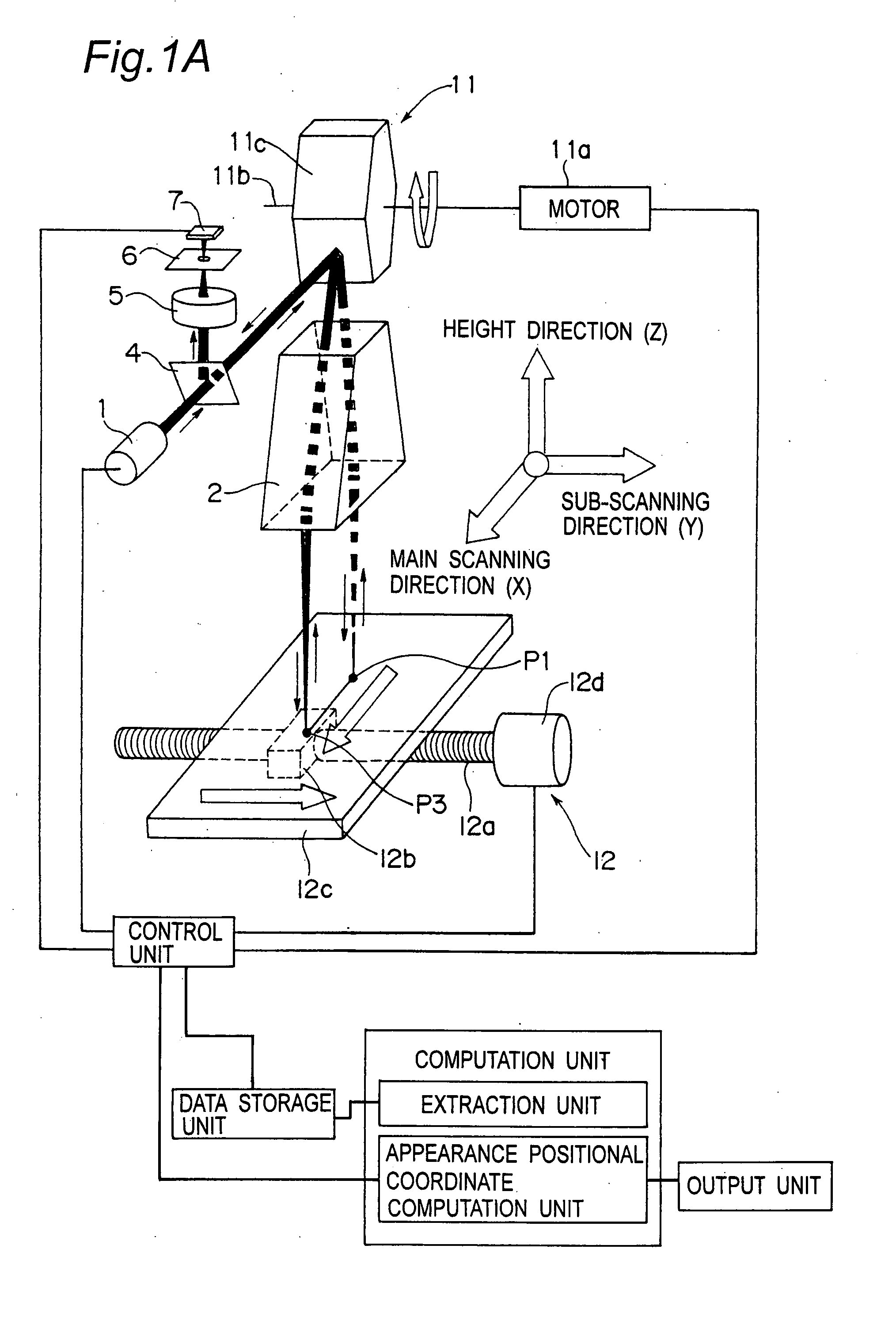
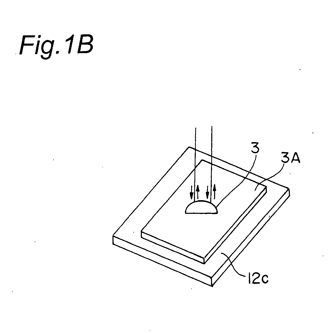
[0081]FIG. 1A is a perspective view schematically showing a configuration of an optical system and a mechanical system of an appearance inspection apparatus according to a first embodiment of the present invention, and FIG. 1B is a partially enlarged perspective view of FIG. 1A showing an inspection object 3. FIG. 2 is a schematic view showing the optical system when viewed from the sub-scanning direction.

[0082]A basic configuration of the appearance inspection apparatus according to the first embodiment of the present invention will be described with reference to FIGS. 1A and 1B. The appearance inspection apparatus according to the first embodiment of the present invention includes a light source 1, a rotating polygon mirror 11, a motor 11a, a scanning collective lens 2 which constitutes an example of collecting point position forming optical system, a light separation mirror 4, a reflected light collective lens 5, a shielding plate 6, a photodetector 7, a table feeding device 12 w...

second embodiment

[0123]FIG. 9A is a schematic view showing a configuration of an optical system of an appearance inspection apparatus and method according to a second embodiment of the present invention when viewed from the sub-scanning direction Y. FIG. 9B is a schematic view showing the configuration of the optical system of the appearance inspection apparatus and method according to the second embodiment of the present invention when viewed from a main-scanning direction X.

[0124]As shown in FIGS. 9A and 9B, the appearance inspection apparatus and method of the second embodiment of the present invention differs from the appearance inspection apparatus of the first embodiment in that the appearance inspection apparatus and method of the second embodiment includes a scanning collective lens 2A and a wedge-shape long prism 15. The scanning collective lens 2A is arranged in parallel with the height direction Z while the optical axis of the scanning collective lens 2 is not inclined by the angle β from...


PUM


Abstract

Rotating polygon mirrors are configured such that angles formed by a rotation axis and mirror surfaces differs from one another in the mirror surfaces in order to shift a collecting point of a scanning light flux in a sub-scanning direction in association with rotation at constant angular speed. A collecting point position forming optical system is configured such that the collecting point is moved in an inspection range Zr in a height direction Z. The XYZ scanning is performed by moving the inspection object in the sub-scanning direction such that the collecting point shifted in the sub-scanning direction and the height direction is linearly scanned in the height direction of the inspection object in synchronization with the rotation of the rotating polygon mirror at the constant angular speed, and the an appearance positional coordinate of the inspection object is determined by a confocal method to perform the appearance inspection.

Description

[0001]The present invention relates to an apparatus and a method for appearance inspection of an inspection object. Particularly the present invention relates to the apparatus, in which the inspection object is irradiated with a spot light (irradiating light) such as a laser beam and is linearly scanned with a focal position forming optical system including a polygon mirror (hereinafter referred to as rotating polygon mirror) and a scanning collective lens, photoelectric conversion is performed from light intensity of reflected light (incident reflected light) which is reflected by the inspection object and deflected by a mirror surface rotating polygon mirror through the focal position forming optical system, and an appearance positional coordinate is determined to inspect an appearance of the inspection object by a principle of a confocal method.[0002]Particularly, because a confocal relationship of the inspection object can be changed during a linear scanning operation performed ...

Claims


Application Information

Patent Timeline
IPC IPC(8): G01N21/55
CPCG01B11/24G01N21/8901G02B26/12G02B5/09G02B21/0048G01N21/8903
Inventor ONO, YUJI
Owner PANASONIC CORP
Why Eureka
Try Eureka