Compound automotive rearview mirror

a rearview mirror and composite technology, applied in the field of mirrors, can solve the problems of inability to view the adjacent lanes, insufficient adjacent lane visibility of the fmvss 111, and inability to observe vehicles with a glance over the shoulder, etc., to achieve the effect of convenient manufacture and low cos

Inactive Publication Date: 2008-09-18
PLATZER GEORGE E
View PDF76 Cites 101 Cited by
  • Summary
  • Abstract
  • Description
  • Claims
  • Application Information

AI Technical Summary

Benefits of technology

[0019]Still another object of the invention is to provide a mirror having a combination of two surfaces of different magnification that is inexpensive and easy to manufacture.

Problems solved by technology

Early in this century however, both inside and outside mirrors were added to automotive vehicles to provide rearward and limited lateral visibility.
However, it is deficient in that it is unable to view the adjacent lanes at distances of less than one to two car lengths to the rear.
Unfortunately, outside mirrors meeting FMVSS 111 still do not provide adequate adjacent lane visibility to view cars that are in the range of one car length to the rear.
Even a glance over the shoulder may not be adequate to observe a vehicle in the blindzone.
Furthermore, this obstruction is not obvious to most drivers, and they may assume that the “over the shoulder glance” has allowed them to see the blindzone when in reality it has not.
Spherically convex mirrors provide a wide field of view, but at the penalty of a reduced image size.
Simply placing a round segment of a convex mirror on the main mirror surface, as is commonly done with stick-on convex mirrors, does not solve the problem.
Doing so can provide a view to the rear which includes the blindzone, but it will also show much of the side of the car, the sky and the road surface, which are distracting and extraneous to the safe operation of the vehicle.
In this way, if the driver sees a vehicle in the blindzone-viewing mirror, he knows it is unsafe to move into the adjacent lane.
Other problems with add-on mirrors are that they:may interfere with the requirements of FMVSS 111;may substantially decrease the plane main mirror viewing angle;interfere with cleaning, especially when there is ice on it; andappear as an unsightly excrescence on the main mirror.

Method used


Image

  • Compound automotive rearview mirror
  • Compound automotive rearview mirror
  • Compound automotive rearview mirror

Examples


Embodiment Construction

)

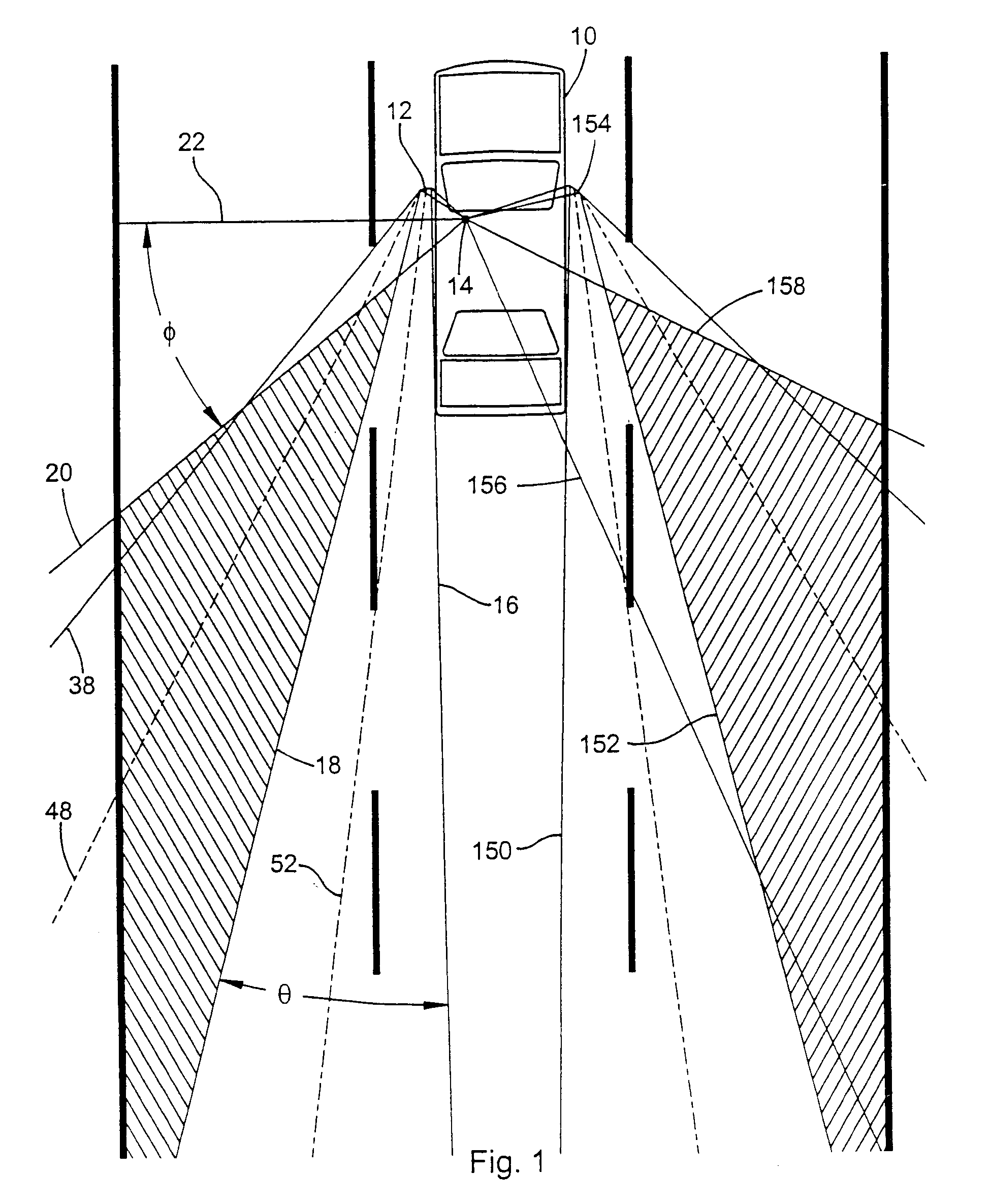
[0112]Referring now in greater detail to the drawings, FIG. 1 shows a mid-sized passenger car 10 in the middle lane of a three-lane highway with 12-foot wide lanes. The vehicle 10 is equipped with a driver's side outside mirror 12. The driver's eyes are shown centered at point 14, from which the driver has a field of view to the rear in the horizontal plane encompassing the acute angle formed by lines 16 and 18. Line 20 defines the rearward limit of the driver's peripheral vision when looking at mirror 12. Thus, the area bounded by lines 18 and 20 is a blindzone, shown crosshatched, which cannot be observed in either the driver's direct forward vision or indirectly in the mirror.

[0113]SAE Technical Paper 950601 describes the horizontal field of view of a plane mirror in a mathematical equation as a function of the mirror's dimensions and the position of the eyes relative to the mirror. Typically, the angle subtended by lines 16 and 18 is in the order of 15° to 20°. Angle θ is given...


PUM


Abstract

A composite mirror adapted for use as an outside rearview mirror of a motor vehicle includes a main or primary viewing mirror and an auxiliary blindzone viewing mirror juxtaposed to expose the vehicle blindzone to the vehicle operator. The main viewing mirror is generally of unit magnification. The auxiliary mirror is composed of a planar array of reflecting facets mimicking a convex mirror. The main and auxiliary mirrors can be combined in constant or variable reflectivity applications.

Description

CROSS-REFERENCE TO RELATED APPLICATION[0001]This application is a divisional of U.S. patent application Ser. No. 10 / 280,042, filed Oct. 24, 2002, which is a continuation-in-part of International Application Serial No. PCT / US01 / 13283, filed on Apr. 24, 2001, that designates the United States of America and was published under PCT Article 21(2) in English, which is a continuation of U.S. patent application Ser. No. 09 / 551,676, filed Apr. 24, 2000, now issued as U.S. Pat. No. 6,315,419 on Nov. 13, 2001, and U.S. patent application Ser. No. 09 / 733,410, filed Dec. 11, 2000, now abandoned.BACKGROUND OF THE INVENTION[0002]1. Field of the Invention[0003]The present invention relates generally to mirrors having multiple surfaces of differing magnification and, particularly, to the application of such mirrors as external side rearview automotive operator aides.[0004]2. Background Art[0005]Originally, motor vehicles, particularly passenger cars, did not have mirrors to assist the driver. Early...

Claims


Application Information

Patent Timeline
Patent Type & Authority Applications(United States)
IPC IPC(8): B60R1/08
CPCB60R1/08B60R1/082
Inventor PLATZER, GEORGE E.
Owner PLATZER GEORGE E
Why Eureka
Try Eureka