Upright inclined-hole drilling jig

Inactive Publication Date: 2008-09-18
CHIANG VANCE
View PDF15 Cites 32 Cited by
  • Summary
  • Abstract
  • Description
  • Claims
  • Application Information

AI Technical Summary

Benefits of technology

[0005]The primary object of the present invention is to provide an improved upright inclined-hole drilling jig, which can rapidly adju

Problems solved by technology

The whole operation is not only troublesome and time consuming, it tends to damage the drill bit.
Moreover, the inclined-hole drilling jig 2 offers only one height, which hardly meets the varying requirements for inclined holes nowadays.
Al

Method used


Image

  • Upright inclined-hole drilling jig
  • Upright inclined-hole drilling jig
  • Upright inclined-hole drilling jig

Examples


Embodiment Construction

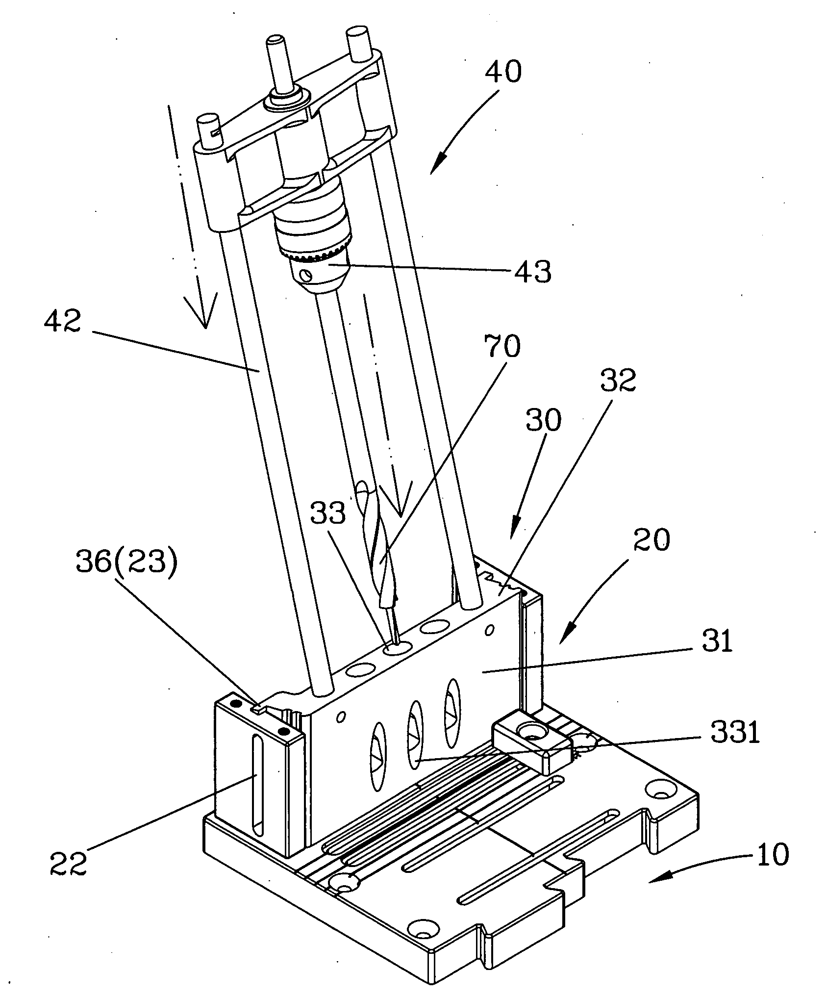
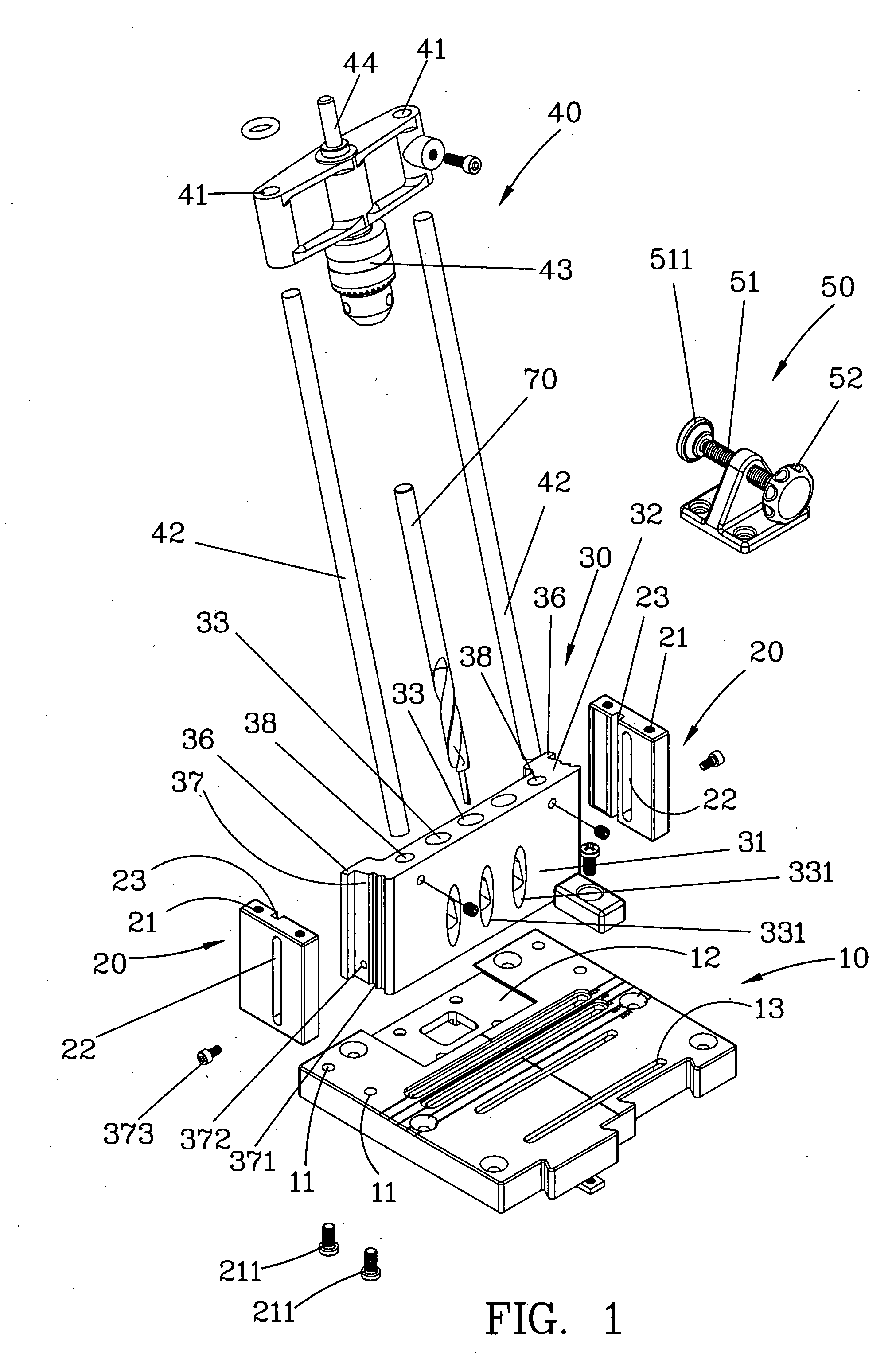
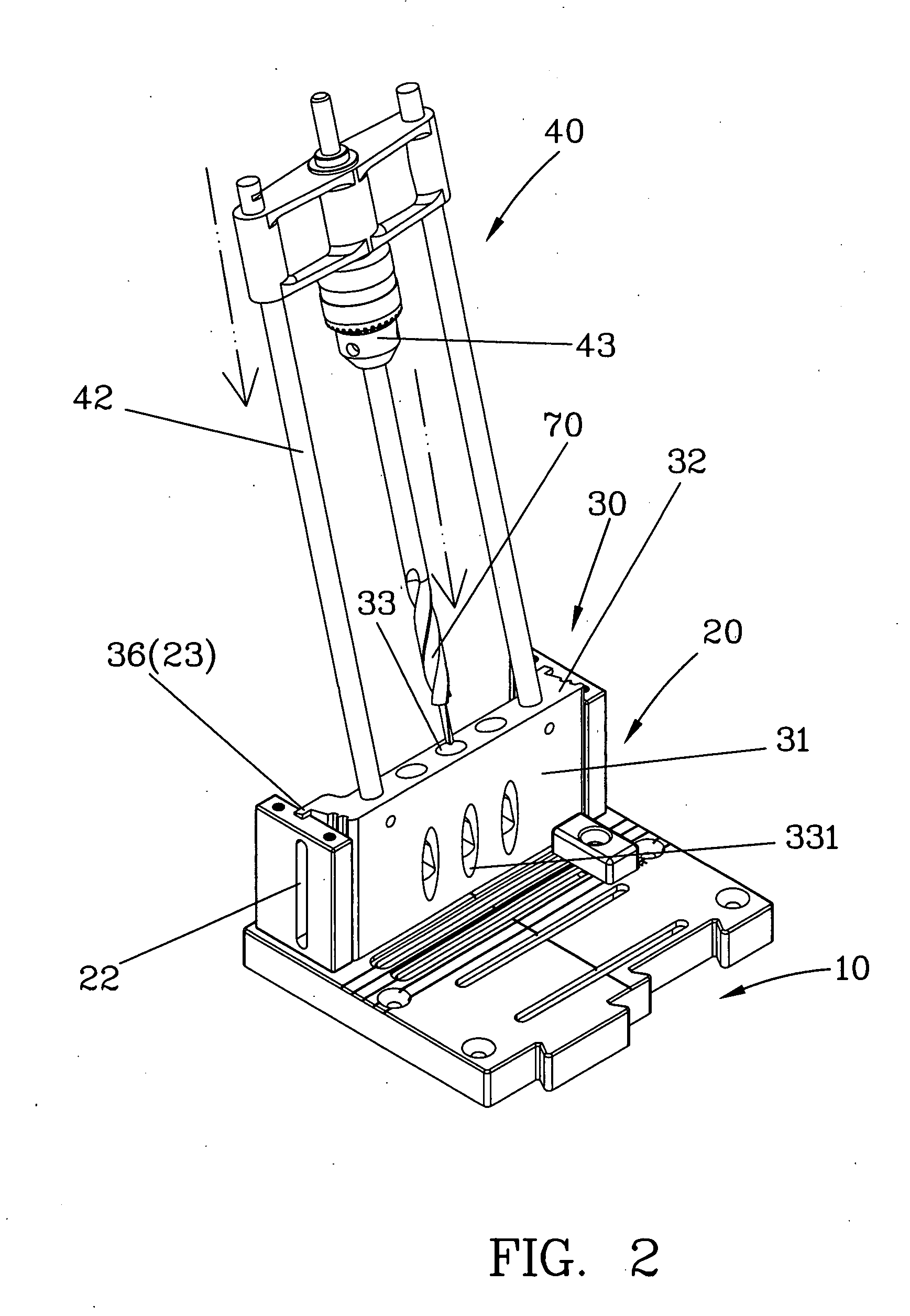
[0016]Referring to FIGS. 1˜6, the improved upright drilling jig of the invention comprises a base platform 10, two parallel panels 20, a drilling jig 30, a sliding saddle 40, and a holder 50.

[0017]The base platform 10 is a horizontal extending board disposed with a set of positioning holes 11 configured on the right and left sides at its axial front end, a receiving concavity 12 at the center of its axial front end, and a plurality of parallel positioning slots 13 at its axial rear end to position and secure other elements such as the holder 50.

[0018]The parallel panel 20 is a rectangular plate concavely disposed with two bolt holes that run through from its top to bottom to allow mounting bolts 211 to screw into the axial front end positioning holes configured on the right and left sides of base platform 10. On the side of the parallel panel 20 opposing to the other parallel panel 20 is each disposed with a perforated limiting slot hole 22. On the plane adjacent to the limiting slo...


PUM

PropertyMeasurementUnit
Thicknessaaaaaaaaaa
Shapeaaaaaaaaaa
Areaaaaaaaaaaa

Abstract

An improved upright drilling jig comprises two parallel panels parallelly mounted on a leveled base platform, and an inclined-hole drilling jig pivotally disposed between the sides of the parallel panels in a manner that it can be vertically adjusted. A sliding saddle is slidably and pivotally mounted at the top of the inclined-hole drilling jig through two axial bars. The rear side of the drilling jig is concavely constricted to form a bow jumper area and disposed with a discharge concavity in a manner approaching a clamping end plane. The discharge concavity has a chip hole inside that communicates with a guide axle hole. Such arrangement can achieve optimum performance of inclined hole drilling of woodwork.

Description

BACKGROUND OF THE INVENTION[0001]1. Field of the Invention[0002]The present invention relates to a DIY woodwork drilling, more particularly, an improved upright inclined-hole drilling jig structure.[0003]2. Description of the Related Art[0004]Inclined-hole drilling of woodwork is primarily used in the corner joint of woodpieces. Conventional techniques commonly use step drill bit having different diameters to drill stepped holes to prevent excess depth of the holes for jointing two woodpieces from affecting the structural integrity of the wood and causing cracks and damages. Step drill bits need to angle obliquely to create a specific inclined hole for bolting and fixation. Drilling of specific inclined holes typically employs an upright inclined-hole drilling jig as shown in FIG. 7. Such drilling jig comprises mainly a horizontal base platform 1 as foundation, and a securely mounted inclined-hole drilling jig 2 and a clamping fixture 3 disposed at two opposing sides of the base pla...

Claims


Application Information

Patent Timeline
IPC IPC(8): B23B47/28
CPCB23B47/287B23B2247/10B23B2247/12Y10T408/567Y10T408/563Y10T408/56245Y10T408/98
Inventor CHIANG, VANCE
Owner CHIANG VANCE
Why Eureka
Try Eureka