Active, micro-well thermal control subsystem

a subsystem and micro-well technology, applied in the field of active, micro-well thermal control subsystems, can solve the problem of limited thermal performance of such systems

Active Publication Date: 2008-09-18
SIEMENS HEALTHCARE DIAGNOSTICS INC
View PDF10 Cites 10 Cited by
  • Summary
  • Abstract
  • Description
  • Claims
  • Application Information

AI Technical Summary

Benefits of technology

[0007]An active thermal control subsystem for controlling the temperature of a sample-containing holding device used in connection with bDNA testing, polymerase chain reaction testing, chemiluminescen

Problems solved by technology

However, thermal performance of such systems is limited b

Method used


Image

  • Active, micro-well thermal control subsystem
  • Active, micro-well thermal control subsystem
  • Active, micro-well thermal control subsystem

Examples


Embodiment Construction

[0016]U.S. Provisional Patent Application No. 60 / 918,190 filed on Mar. 15, 2007 and entitled “Active, Micro-well Thermal Control Subsystem”, from which priority is claimed, is incorporated herein by reference.

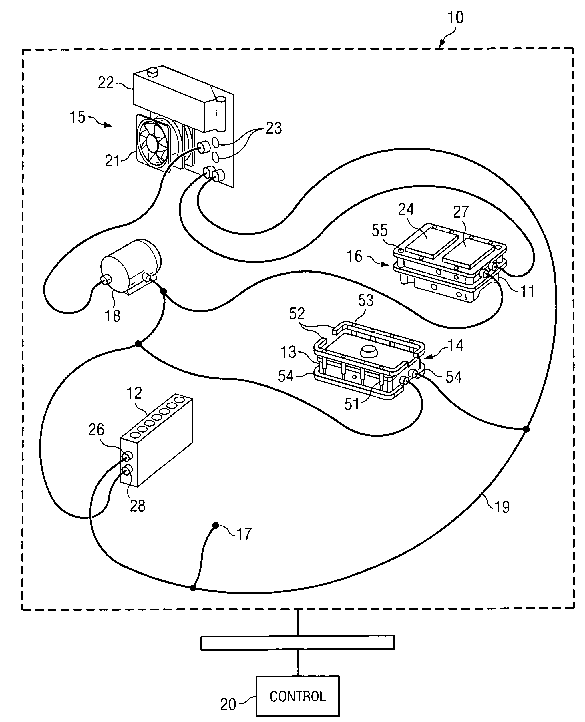
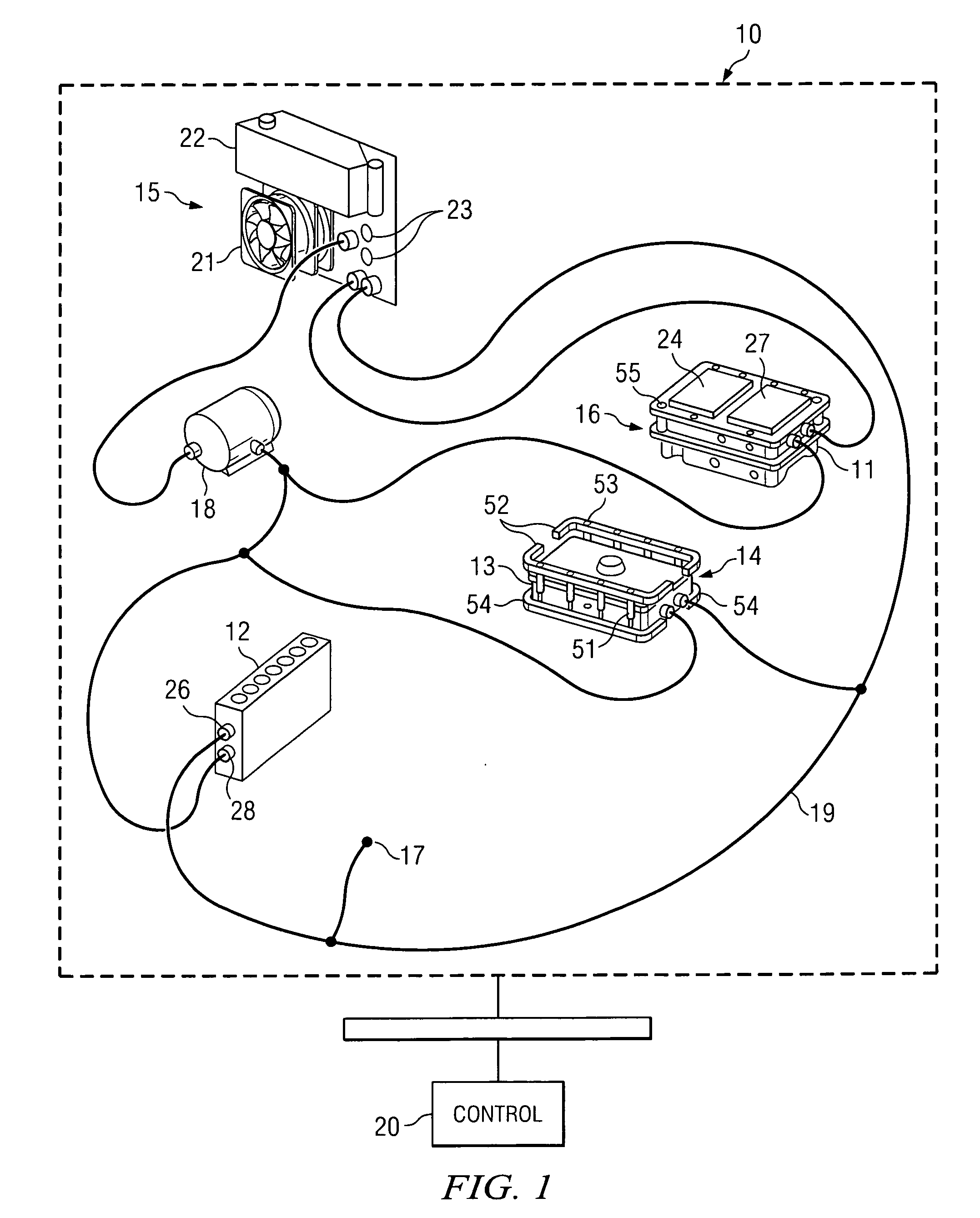
[0017]An active control, micro-well thermal breadboard / micro-well thermal subsystem, e.g., for a bDNA testing system, a chemiluminescent immunoassay system, a PCR testing system, and the like, is disclosed. Referring to FIG. 1, there is shown an active thermal control subsystem 10 for controlling the temperature of at least one micro-well assay tray (not shown). The micro-well assay tray discussed in this disclosure corresponds to a conventional micro-well titer plate for holding multiple, i.e., 96, sample-containing cuvettes. The invention, however, is applicable to other sample-holding devices.

[0018]The subsystem 10 is structured and arranged to maintain micro-well plate incubation temperatures between about 20 degrees Centigrade (° C.) and about 70° C., which is to say, betw...


PUM


Abstract

Devices and systems for active thermal control of sample holding devices for bDNA testing, polymerase chain reaction testing, chemiluminescent immuno-assay testing, and so forth. The thermal control subsystem includes a fluidic circuit, first and second heater assemblies, a centrifugal pump, and a heat exchange device. The first and second heater assemblies include a heat removal device and a controllable thermo-electric device. One or both of the heater assemblies can include a heat spreader. A controller actively controls the pump, the heat removal device, and the thermo-electric devices, to thermally-control sample-containing vessels retained in the holding device.

Description

CROSS REFERENCE TO RELATED APPLICATIONS[0001]Pursuant to 35 U.S.C. § 119(e), a right of priority to U.S. Provisional Patent Application No. 60 / 918,190 filed on Mar. 15, 2007 and entitled “Active, Micro-well Thermal Control Subsystem” is asserted.STATEMENT REGARDING FEDERALLY SPONSORED RESEARCH OR DEVELOPMENT[0002](Not Applicable)BACKGROUND OF THE INVENTION[0003]The present invention relates to devices and systems for providing active thermal control of sample-containing assay trays and, more specifically, to devices and systems that provide improved, uniform heat transfer from a sample-containing assay tray using thermo-electric devices, heat spreader plates, and liquid heat exchangers.[0004]Protocols for amplification of RNA or DNA, for example, during polymerase chain reaction (PCR), bDNA, and similar testing, require rapid and uniform heating and cooling of a plurality of sample-containing vessels. Because such testing typically is performed in batches, the rapid and uniform heat...

Claims


Application Information

Patent Timeline
IPC IPC(8): C12M1/02
CPCB01L7/52B01L2200/147B01L2300/0829F25B21/04B01L2300/1844B01L2300/185B01L2300/1822
Inventor POLANIEC, JIMLAPEUS, DAVID J.GRESZLER, TIMKLINGSHIRN, FRANKSTURGES, CHRISSCHMIDT, MATT
Owner SIEMENS HEALTHCARE DIAGNOSTICS INC
Why Eureka
Try Eureka