Hydraulic Actuator Control System

a control system and hydraulic actuator technology, applied in the direction of fluid couplings, instruments, packaged goods, etc., can solve the problems of large forces, large forces, and many challenges associated with the use of automated refuse loaders

Inactive Publication Date: 2008-09-18
HARTFIEL AUTOMATION
View PDF35 Cites 75 Cited by
  • Summary
  • Abstract
  • Description
  • Claims
  • Application Information

AI Technical Summary

Benefits of technology

[0009]One embodiment of the invention is to a system for controlling motion of a hydraulic actuator during a portion of its range of motion. The system includes a sensor on the hydraulic actuator for providing a signal indicating that the actuator is near the portion of its range of motion, and a pneumatic control valve that is configured to selectively modify a pressurized air contr

Problems solved by technology

However, there are various challenges associated with the use of automated refuse loaders.
However, when a refuse loader mechanism operates at high speed, large forces will be created if the mechanism suddenly comes to a stop or change direction.
These forces can be very large, particularly when the loader mechanism is lifting a dumpster or other refuse container that can weigh in excess of several tons.
These large forces can result in large stresses within mechanical components, leading to breakage, failure, or accelerated wear of components, or can result in pressure spikes in hydraulic components, also leading to breakage and failure of components.
In any case, rapidly stopping a refuse loader mechanism, and thereby also rapidly stopping whatever load the mechanism is carrying, can cause significant forces to be imparted to the mechanism and the rest of the machine.
Other types of hydraulic actuators, such as rotary hydraulic actuators, also have a range of travel, and can also cause sign

Method used


Image

  • Hydraulic Actuator Control System
  • Hydraulic Actuator Control System
  • Hydraulic Actuator Control System

Examples


application examples

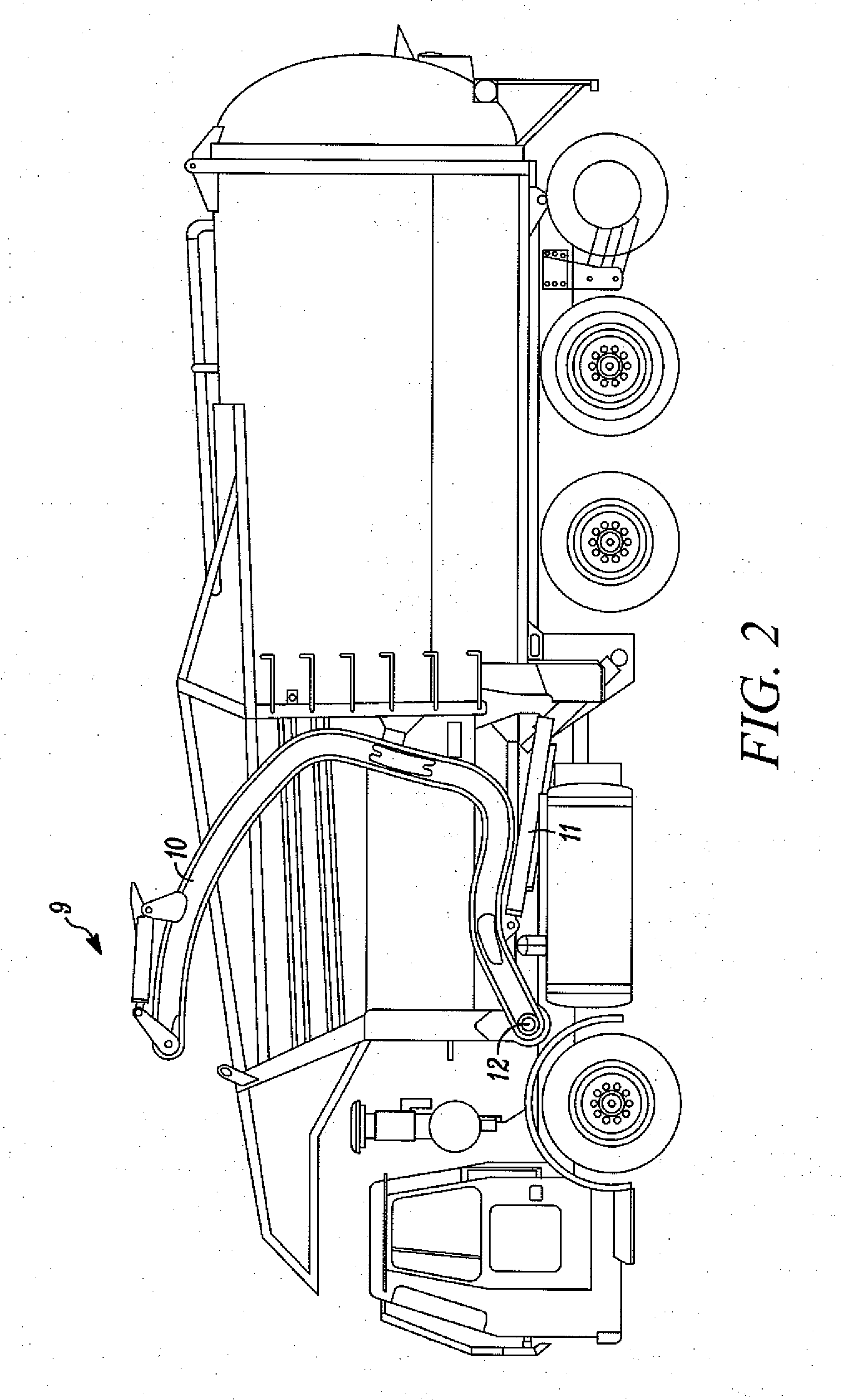
[0064]The application of the hydraulic actuator control system to a variety of refuse collection vehicles will now be described. These applications are merely examples of how the hydraulic actuator control system can work in a few specific refuse collection vehicles. There are many different varieties of refuse collection vehicles with many different configurations for loading refuse. The hydraulic control system can be applied to and catered to many different refuse collection vehicles and loading configurations. The full variety of features of these vehicles, their different loading systems, and the catering of the hydraulic control system will not be discussed herein, but rather the configuration of a few specific examples will be described.

Side Loading Recycling Vehicle

[0065]A side loading recycling vehicle, such as vehicle 14 shown in FIG. 3, includes collection buckets 16. Throughout the collection route, the operator places items into the collection buckets 16. The unloading ...


PUM


Abstract

A system for controlling motion of a hydraulic actuator during a portion of its range of motion is described, including a sensor on the hydraulic actuator for providing a signal indicating that the actuator is near a portion of its range of motion, and a pneumatic control valve that is configured to selectively modify a pressurized air control signal to in turn restrict flow of pressurized hydraulic fluid to the hydraulic actuator. The hydraulic actuator control system further includes an electronic controller for controlling the pneumatic control valve in response to a signal from the sensor. The hydraulic actuator control system thereby slows the motion of the hydraulic actuator near the portion of its range of motion.

Description

RELATED APPLICATIONS[0001]This application is a non-provisional application of U.S. Provisional Application No. 60 / 895,150, filed Mar. 16, 2007, the entire contents of the U.S. application is incorporated herein by reference.FIELD OF THE INVENTION[0002]The invention relates to control systems for hydraulic actuators, and more particularly, to the control of hydraulic actuators at certain positions in their range of travel.BACKGROUND OF THE INVENTION[0003]To increase the efficiency of refuse collection, many refuse collection companies use automated refuse loaders that lift a refuse container and then dump the refuse container into a refuse collection vehicle. Such automated refuse loaders can service a significantly higher number of customers in a given time period when compared with manually placing refuse into the refuse collection vehicle. This increased efficiency can result in substantially lower refuse collection costs. However, there are various challenges associated with the...

Claims


Application Information

Patent Timeline
IPC IPC(8): G06F17/00B65F3/02
CPCB65F3/06
Inventor LAUMER, STEVE P.LAGRO, GARY LEE
Owner HARTFIEL AUTOMATION
Why Eureka
Try Eureka