Vehicle suspension system and method of operating same

a suspension system and vehicle technology, applied in the field of vehicle suspension systems, can solve the problems of introducing certain problems and/or disadvantages, prior art suspension systems are known to undertake height adjustment and/or leveling activities, and it is undesirable to undertake a height adjustment or leveling action under such a condition

Active Publication Date: 2008-09-18
DRIVERIGHT HLDG
View PDF26 Cites 23 Cited by
  • Summary
  • Abstract
  • Description
  • Claims
  • Application Information

AI Technical Summary

Benefits of technology

[0015]One embodiment of a suspension system in accordance with the subject matter of the present disclosure for use on an associated vehicle is provided that is adapted to support an associated sprung mass on an associated unsprung mass of the associated vehicle. The associated vehicle includes a longitudinally extending midline and left and right sides relative to the midline. The associated unsprung mass includes a front axle, a first rear axle, and a second rear axle. The suspension system includes a first left gas spring and a first right gas spring respectively disposed along left-side and right-side portions of the first rear axle. A second left gas spring and a second right gas spring are respectively disposed along left-side and right-side portions of the second rear axle. A pressurized gas system includes a pressurized gas source that is adapted to provide pressurized gas and a control device that is capable of selectively placing the gas springs in fluid communication with one of the pressurized gas source and a pressurized gas exhaust. A first set of height sensors is provided and capable of outputting signals having a relation to relative distances between the first rear axle and the associated sprung mass. The first set of height sensors include a first left height sensor operatively connected along the left-side portion of the first rear axle and a first right height sensor operatively connected along the right-side portion of the first rear axle. A second set of height sensors is provided and capable of outputting signals having a relation to relative distances between the second rear axle and the associated sprung mass. The second set of height sensors includes a second left height sensor operatively connected along the left-side portion of the second rear axle and a second right height sensor operatively connected along the right-side portion of the second rear axle. And, a controller is operatively connected to the first and second sets of height sensors for receiving the signals therefrom and operatively connected to the control device for selectively inflating or deflating respective ones of the gas springs to thereby adjust a leveled orientation of the associated sprung mass. The controller also stores a vertical offset threshold and an articulation offset threshold, and is adapted to determine one or more relative distances between the associated sprung mass and at least one of the first and second rear axles based on the signals from at least a corresponding one of the first and second sets of height sensors. The controller is further adapted to determine that a condition exists for adjusting the leveled orientation of the associated sprung mass based at least in part on the one or more relative distances. The controller is also adapted to calculate a first rear axle to second rear axle vertical offset (RAVO) and a first rear axle to second rear axle articulation offset (RAAO) based at least in part on the one or more relative distances. The controller is also adapted to compare the RAVO to the vertical offset threshold and compare the RAAO to the articulation offset threshold. Upon determining that both of the RAVO and the RAAO are less th

Problems solved by technology

However, such prior art suspension systems can also introduce certain problems and/or disadvantages that can be associated with or otherwise related to the actions of adjusting the position and/or orientation of the sprung mass relative to the unsprung mass of the vehicle.
One such disadvantage is that prior art suspension systems are known to undertake height adjustment and/or leveling activities under conditions of operation in which it may be less desirable to do so, such as conditions in which the vehicle is undergoing a temporary or otherwise short term variation in height, for example.
However, in many situations, such a condition will be a transient or ot

Method used


Image

  • Vehicle suspension system and method of operating same
  • Vehicle suspension system and method of operating same
  • Vehicle suspension system and method of operating same

Examples


Embodiment Construction

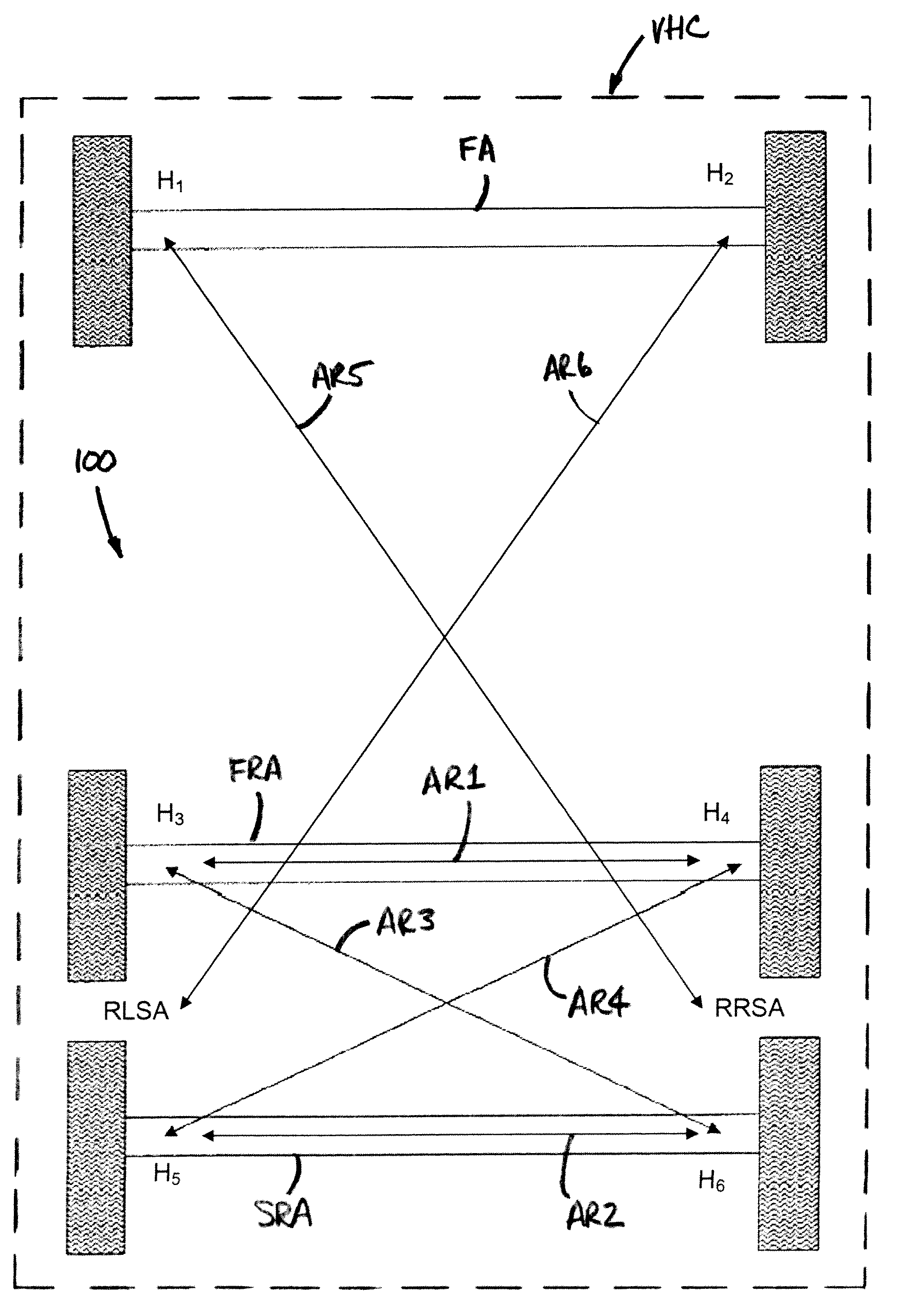
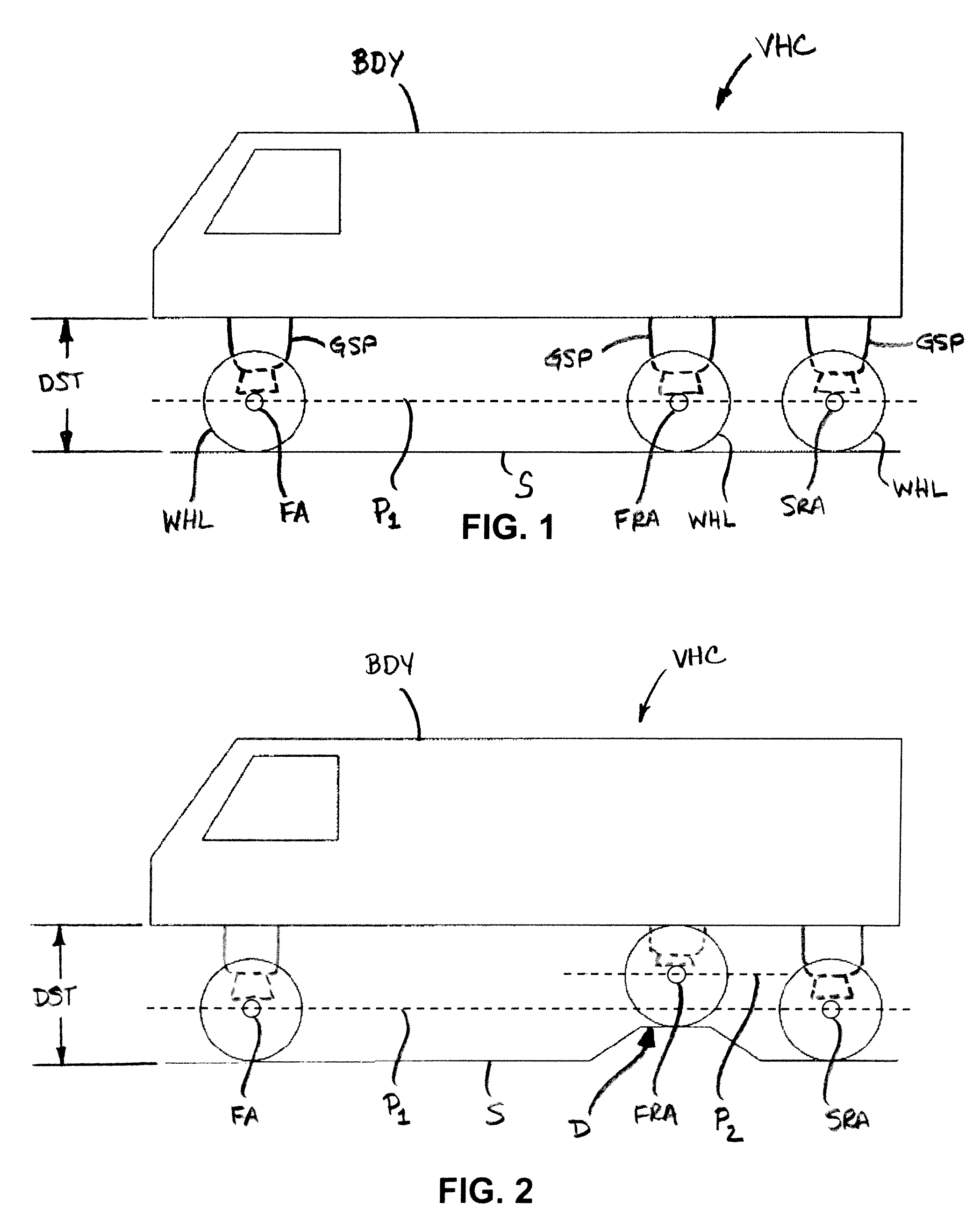
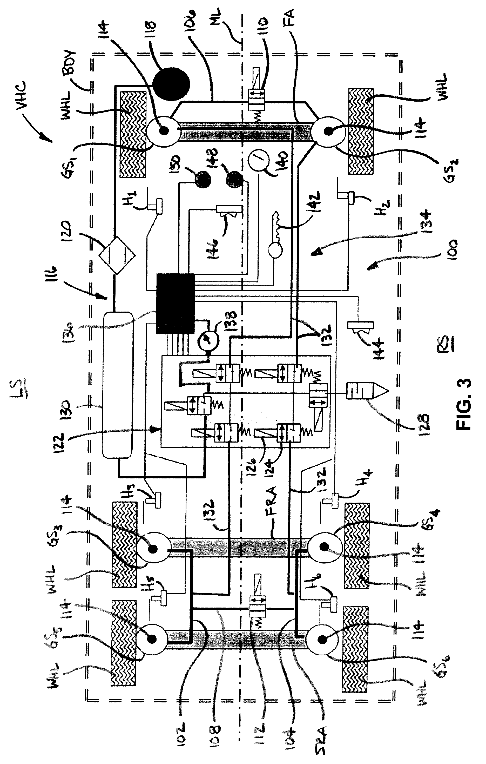
[0027]Turning now to FIGS. 3-9, wherein the showings are for the purpose of illustrating exemplary embodiments of the present novel concept and not for the purpose of limiting the same, FIG. 3 illustrates an embodiment of a suspension system 100 disposed in operative association between a sprung mass, such as an associated vehicle body BDY, for example, and an unsprung mass, such as an associated wheel WHL, an associated front axle FA, an associated first rear axle FRA and an associated second rear axle SRA, for example, of an associated vehicle VHC. For the sake of clarity, suspension system 100 will be described herein with reference to a longitudinally-extending midline ML that generally defines a transition between a left side LS and a right side RS of the associated vehicle.

[0028]With continued reference to FIG. 3, suspension system 100 includes a plurality of gas spring assemblies GS1-GS6 with a different one of the plurality of gas spring assemblies disposed along a respectiv...


PUM


Abstract

A suspension system for use on a vehicle having two or more rear axles. The suspension system includes a plurality of gas springs and plurality of height sensors capable of outputting signals having a relation to distances between the respective ends of the respective first and second rear axles and the sprung mass of the vehicle. A control system adapted to selectively inflate or deflate respective ones of the plurality of gas springs to thereby adjust a leveled orientation of the sprung mass. The control system includes a controller that is adapted to determine a rear axle vertical offset and a rear axle articulation offset. The controller is adapted to determine whether conditions are appropriate for adjusting the suspension system by comparing the rear axle vertical offset and/or the rear axle articulation offset to a corresponding vertical offset threshold and/or an articulation offset threshold. A method is also included.

Description

[0001]This application claims priority from U.S. Provisional Patent Application No. 60 / 906,368 filed on Mar. 12, 2007, the entire disclosure of which is hereby incorporated by reference herein. Additionally, the entire disclosure of U.S. patent application Ser. No. 11 / 705,916 filed on Feb. 13, 2007, which is entitled VEHICLE SUSPENSION SYSTEM AND METHOD, under Attorney Docket Nos. P06002US2A / FIRZ 2 00243, is also hereby incorporated herein by reference.BACKGROUND[0002]The subject matter of the present disclosure broadly relates to the art of vehicle suspension systems and, more particularly, to a suspension system and method of operating the same for a vehicle having two or more rear axles. Such a system and method being capable of at least adjusting a height and / or orientation of the vehicle based at least in part on the relative position and / or orientation of the two or more rear axles with respect to one another and, optionally, with respect to the front axle of the vehicle.[0003...

Claims


Application Information

Patent Timeline
IPC IPC(8): B60G17/018B60G17/04
CPCB60G17/0155B60G2800/914B60G17/018B60G17/019B60G21/10B60G2202/152B60G2204/80B60G2300/0262B60G2400/252B60G2500/30B60G2600/02B60G2600/07B60G2600/12B60G2800/912B60G17/0165
Inventor BROOKES, GRAHAM RBOUNDS, JOSEPH AHOLBROOK, GREGORY A
Owner DRIVERIGHT HLDG
Why Eureka
Try Eureka