Storage system and method of storage system path control

a storage system and path control technology, applied in the field of storage system and a method of storage system path control, can solve the problems of ineffective use waste of old type of storage device, and achieve the effect of improving ease of use and reliability, and effective use of storage resources

Inactive Publication Date: 2008-09-18
HITACHI LTD
View PDF9 Cites 92 Cited by
  • Summary
  • Abstract
  • Description
  • Claims
  • Application Information

AI Technical Summary

Benefits of technology

[0009]With the foregoing in view, it is an object of the present invention to provide a storage system and a method of storage system path control to link together a plurality of storage devices to enable effective use of storage resources, and improved ease of use and reliability. A further object of the present invention is to provide a storage system and a method of storage system path control to connect a plurality of storage devices via a plurality of communications paths and enable switching of the communications path in response to the state of use of the storage system. Further purposes of the present invention will be apparent from the embodiments disclosed below.
[0014]In an embodiment of the present invention, the control section also has a failure detector to detect whether or not a failure has occurred in any of the communications paths. When the failure detector detects occurrence of a failure in a communications path in use, at least one of the usable communications paths is selected and used. In other words, when any form of failure is detected in a communications path in use, the control section can select a communications path having a high priority from the plurality of normal communications paths. However, selection is not limited to this, and any one of the normal communications paths, or a plurality of communications paths, can be selected as desired. Thus, when a failure occurs in communications path in use and the communications path is no longer usable, the control section can use another communications path to access the actual volume, and processing of access requests from the host is not interrupted. Furthermore, recovery from a failure can be conducted while processing access requests from the host.
[0020]Thus, by establishing a configuration wherein the configuration of each communications path may be managed with the prescribed unit, efficiency of maintenance work may be improved. For example, when a failure occurs, or with work such as planned replacement of components, it is possible to disconnect (logical disconnect) only the communications path on which the failure has occurred, or replacement is planned. Except in cases such as all communications paths being unusable, processing of access requests from the host is not interrupted.
[0022]The control section is further comprised of a failure detector to detect whether or not a failure has occurred in each communications path. When a failure is detected in any of the communications paths, the failure detector may be configured to ignore a failure occurring in a communications path in which the state is set to unusable. Thus, for example, when conducting maintenance work on the second storage device, detected failures can be ignored by presetting the state of the each communications path subject to maintenance work to unusable. A situation wherein failures detected due to planned maintenance work on the second storage device are notified to an external maintenance management center can therefore be prevented before the event.
[0024]In an embodiment of the present invention, the control section can also process access requests while switching each communications path in sequence. In other words, the control section can access the actual volume using a different communications path for each access request. Thus, processing is possible at a higher speed than when access requests are processed using a single communications path.

Problems solved by technology

However, when data has been completely transferred, the old type of storage device is wasted, and the old type of storage device cannot be used effectively.

Method used


Image

  • Storage system and method of storage system path control
  • Storage system and method of storage system path control
  • Storage system and method of storage system path control

Examples


first embodiment

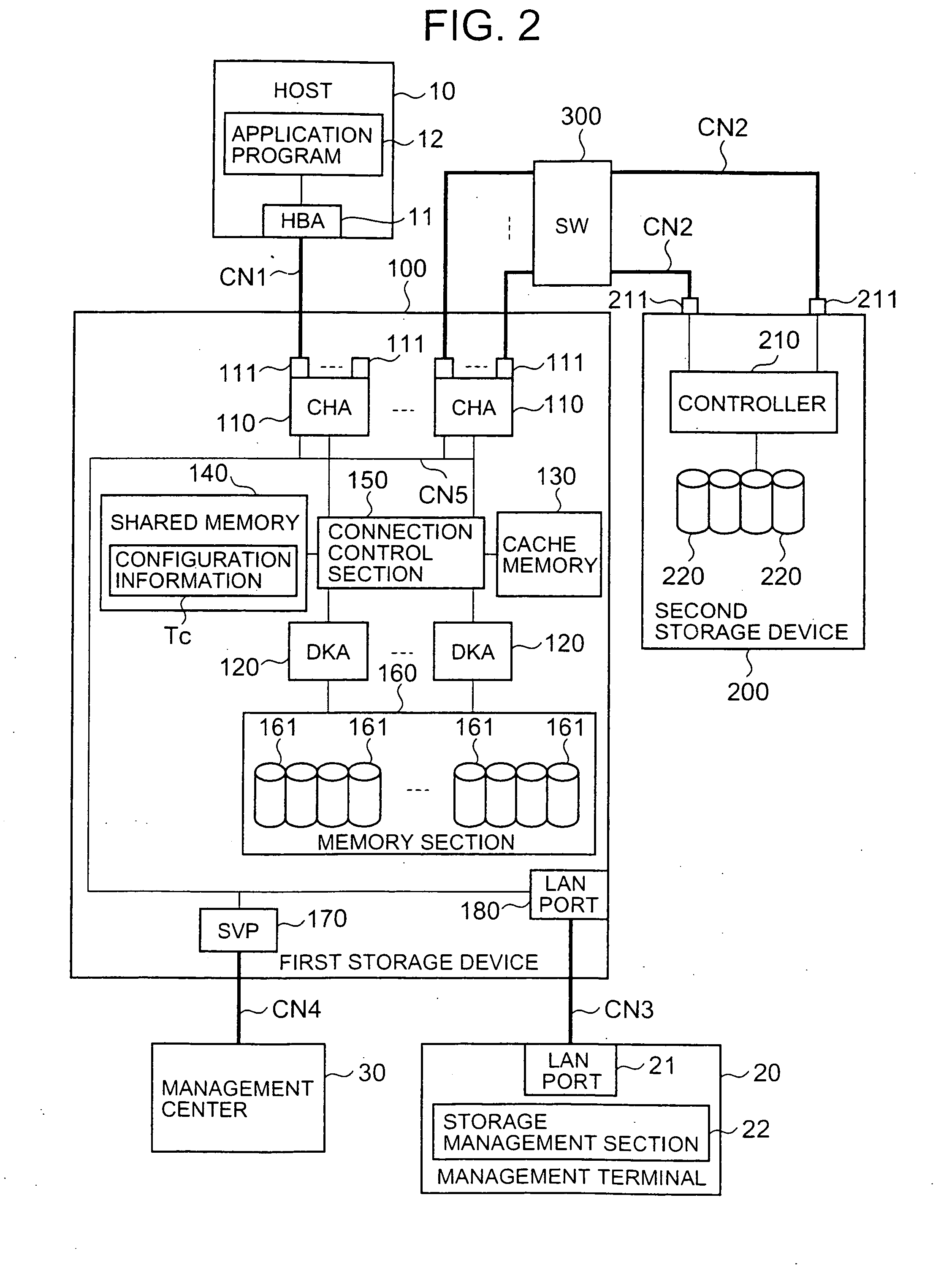
[0077]FIG. 2 is a block diagram showing the configuration of the primary components of the storage system. As described below, this storage system can be, for example, configured to include a host 10, a management terminal 20, a management center 30, a plurality of storage devices 100 and 200, and a switch 300 connecting storage devices 100 and 200.

[0078]The host 10 and first storage device 100 are connected via the communications network CN1. The first storage device 100 and the second storage device 200 are connected via a plurality of communications networks CN2.

[0079]The first storage device 100 and the management terminal 20 are connected via the communications network CN3. Furthermore, the first storage device 100 and the management center 30 are connected via the communications network CN4.

[0080]The host 10 is a computer device comprising information processing resources such as a CPU (Central Processing Unit) and a memory and the like, and is configured as a personal compute...

second embodiment

[0181]The second embodiment is described based on FIG. 13 through FIG. 15. The following embodiments, including the present embodiment, are equivalent to variations of the first embodiment. In the present embodiment, the first storage device 100 and the second storage device 200 are connected by a plurality of paths, and access requests from the host 10 are processed while these paths are selected in sequence.

[0182]FIG. 13 shows an example of the WWN information management table T3. The WWN information management table T3 is information for the management of the alternate path mode (use mode) of the second storage device 200 being external storage.

[0183]The alternate path mode, can be, for example, the single path mode, or the multi-path mode. The single path mode is a mode wherein one of a plurality of paths is selected for use as described in the first embodiment. The multi-path mode is a mode wherein a plurality of paths are selected in sequence for use as described below.

[0184]T...

third embodiment

[0192]The third embodiment is described based on FIG. 16 through FIG. 19. In this embodiment, path operation is possible in prescribed units.

[0193]FIG. 16 a flowchart showing an outline of path operation processing. This processing can be executed with the storage management section 22 of the management terminal 20. Firstly, the user calls up the path configuration processing screen (S110), and selects from the menu (S111).

[0194]The operation menu can be, for example, a menu for manipulating path configuration in units of external ports, a menu for manipulating path configuration in units of external storage ports, or a menu for manipulating path configuration in units of external volumes 240.

[0195]When the user desires to process in units of external ports, the user selects the external port to be manipulated (S112). The management terminal 20 displays the configuration of all paths connected to the external port in a list format (S113). The user selects all or some of the displaye...


PUM


Abstract

The present invention uses memory resources effectively and connects each storage device by a plurality of paths in a switchable manner, thus improving reliability and ease of use, by virtualizing external memory resources as internal memory resources. External storage 2 is connected to the main storage 1, and the actual volume 2A is mapped onto the virtual volume 1A. A plurality of paths is connected between the storage 1 and 2. When a failure occurs in a path in use (S3), the path having the next highest priority is selected (S4), and processing is continued using this path (S5).

Description

CROSS-REFERENCE TO RELATED APPLICATIONS[0001]The present application is a continuation of application Ser. No. 11 / 070,182, filed Mar. 3, 2005; which relates to and claims priority from Japanese Patent Application No. 2004-372713 filed on Dec. 24, 2004, the entire disclosure of which is incorporated herein by reference.BACKGROUND OF THE INVENTION[0002]The present invention relates to a storage system and a method of storage system path control.[0003]For example, in order to handle large volumes of various types of data in government, public offices, local authorities, industry, and educational institutions and the like, comparatively large-scale storage systems are used in management of data. These storage systems are, for example, comprised of disk array devices and the like. Since a disk array device is comprised of a plurality of storage devices arranged in an array, for example, a storage area based on a RAID (Redundant Array of Independent Disks) is provided.[0004]At least one l...

Claims


Application Information

Patent Timeline
Patent Type & Authority Applications(United States)
IPC IPC(8): G06F3/00
CPCG06F3/0614G06F3/0635G06F11/201G06F11/2005G06F3/067
Inventor YAGI, SHUICHITANINAKA, DAIMASHIMA, TAKAO
Owner HITACHI LTD
Why Eureka
Try Eureka