Portable Data Storage Device Using a Memory Address Mapping Table

Inactive Publication Date: 2008-09-18
TREK TECH SINGAPORE PTE
View PDF9 Cites 113 Cited by
  • Summary
  • Abstract
  • Description
  • Claims
  • Application Information

AI Technical Summary

Benefits of technology

[0028]Preferably, the data storage device is capable of distinguishing which logical addresses are particularly likely to have data written to them very often (i.e. it performs a pattern recognition

Problems solved by technology

Firstly, the present inventors have noticed that generally the logical addresses generated by a conventional operating system on the host computer tend to be statistically correlated, which mean

Method used


Image

  • Portable Data Storage Device Using a Memory Address Mapping Table
  • Portable Data Storage Device Using a Memory Address Mapping Table
  • Portable Data Storage Device Using a Memory Address Mapping Table

Examples


first embodiment

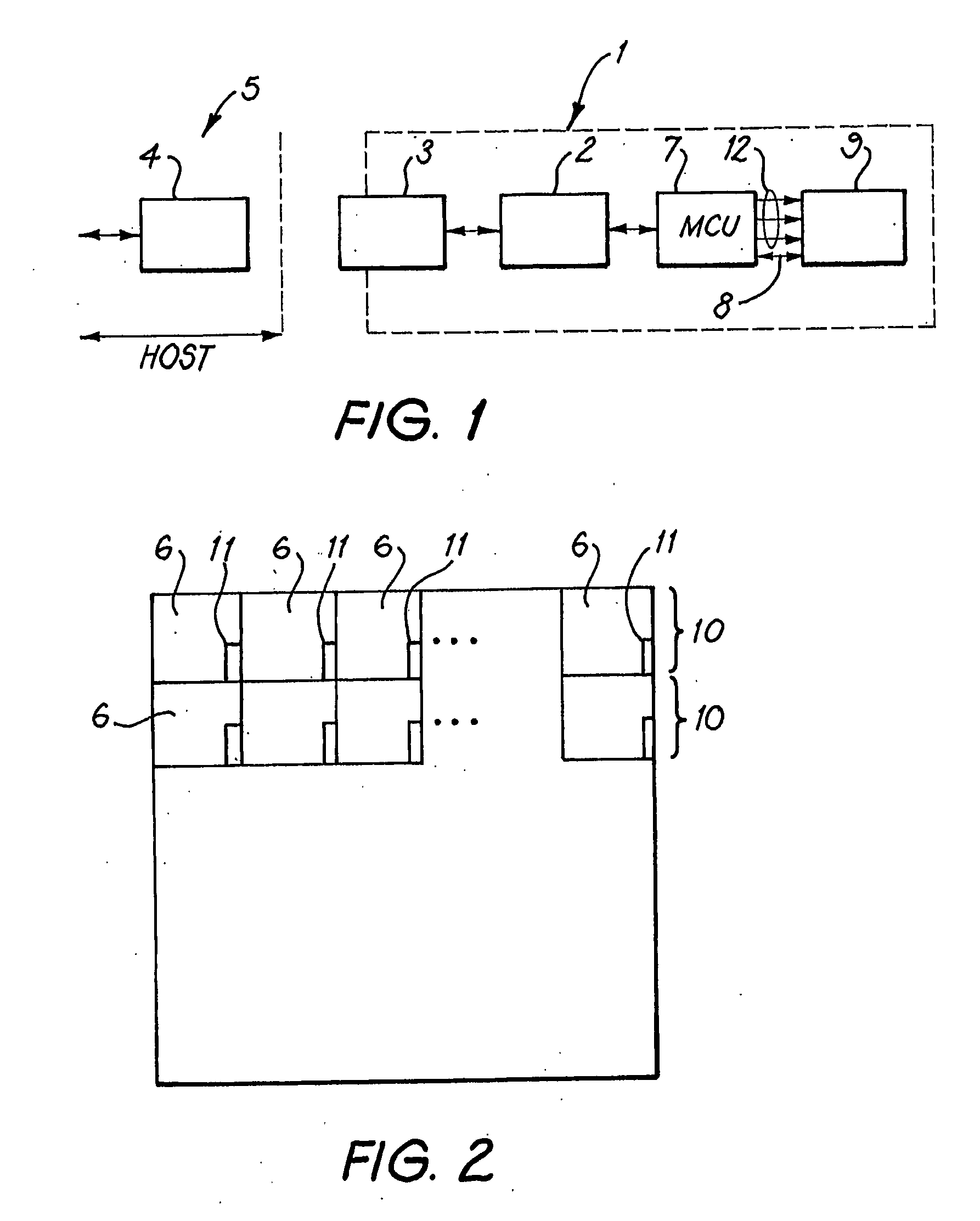
[0055]the invention will now be described. It may have the same physical structure as shown in FIG. 1, and for that reason the corresponding elements of the embodiment will be given the same reference numerals as used in FIG. 1. All the elements shown may be contained in a single housing, e.g. one on which the USB connector 3 is mounted. The USB connector 3 (e.g. USB plug) may be connected directly to a host computer (e.g. a personal computer (PC)) by plugging in to a USB socket 4 of the host computer 5. Alternatively, a cable may be attached between them. It should be noted that this device may have many features which are not shown explicitly in FIG. 1, but which are known in other publicly-available portable data storage devices, such as password protection, access controlled by fingerprint verification, etc. The implementation of such features will be clear to one skilled in the art.

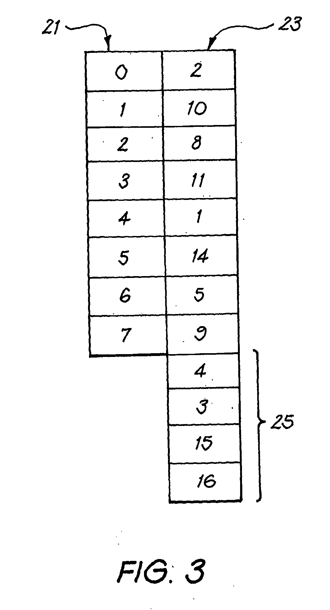
[0056]FIG. 3 shows the memory address mapping table used by the first embodiment. This table is s...

second embodiment

[0079]This describes how the second embodiment operates the mapping between logical address regions and respective groups of blocks. A logically separate issue is how the embodiment maps logical addresses within any given logical address region to respective pages in the corresponding group of blocks.

[0080]One possibility is for the correspondence to be what we will call “horizontal”. This means that the consecutive pages of the blocks to correspond to consecutive logical addresses. The final page of each block (except the last block of the group) corresponds to the logical address consecutively before the logical address corresponding to the first page of the next block of the group. Thus, for example, an amount of data which is slightly larger than the number of pages of a single block, will be written to the memory such that the beginning of the data is written to a page specified by a logical address, then consecutive pages of the block are written to until the block is exhauste...

third embodiment

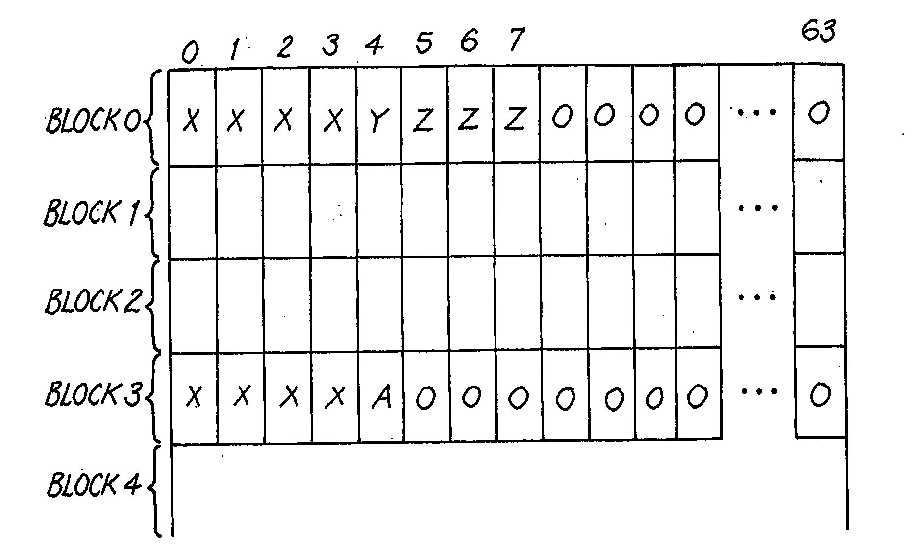
[0088]However, in the invention the physical memory is instead initially rewritten to be as shown in FIG. 7(c). That is, the data A is written to page 4 of block 3, and the data X is copied to pages 0 to 3, but the data Z is not yet copied to pages 5 to 7 of block 3. The system remains in this configuration for a time period given by a timer. If by the end of this period no further WRITE signal has been received in respect of the logical address corresponding to page 5 of block 3, then the write operation is completed to give the data storage shown in FIG. 7(b). However, if during this period a new WRITE instruction is received which indicates that data B is to be stored at the logical address now corresponding to page 5 of block 3, then this data B is written to page 5 of block 3, giving the data storage shown in FIG. 7(d). The timer is then started again to define a new time period.

[0089]If by the end of this period no further WRITE signal has been received in respect of the logic...


PUM


Abstract

A portable data storage device includes a USB controller, a master control unit and a NAND flash memory device. The master control unit receives data to be written to logical addresses, and instructions to read data from logical addresses. It uses a memory address mapping table to associate the logical addresses with the physical addresses in the memory device, and writes data to or reads data from the physical address corresponding to the logical address. The mapping is changed at intervals, so that different ones of the physical address regions are associated at different times with the logical addresses. This increases the speed of the device, and also means that no physical addresses are rapidly worn out by being permanently associated with logical addresses to which data is written relatively often.

Description

FIELD OF THE INVENTION[0001]The present invention relates to portable data storage devices, and methods of employing the devices for storing and retrieving data written to them.BACKGROUND OF INVENTION[0002]During the past couple of years, there has been much interest in providing a data storage devices containing a flash memory and which can be connected to the serial bus of a computer. A leading document in this field is WO 01 / 61692, which describes a one-piece device subsequently marketed under the trade mark “Thumbdrive”. In one of the embodiments described in this document a male USB plug mounted on the housing of the device connects directly to a female USB socket in a computer, so that the computer is able to transfer data to and from the flash memory of the portable storage device under the control of a USB controller. Various improvements have been proposed to this device. For example, WO03 / 003282 discloses that the device may be provided with a fingerprint sensor, and that ...

Claims


Application Information

Patent Timeline
IPC IPC(8): G06F12/02G06F13/12G06F21/00G06K19/07G11B11/00
CPCG06F12/0246G06F2212/7211G06F2212/1036G06F21/32
Inventor TAN, HENRYPOO, TENG PINLIM, LAY CHUAN
Owner TREK TECH SINGAPORE PTE
Why Eureka
Try Eureka