Exhaust Emission Control Device

a technology of emission control device and exhaust gas, which is applied in the direction of heat measurement, separation process, instruments, etc., can solve the problems of reducing affecting the efficiency of the emission control device, and rarely having a chance to reach the temperature level at which the particulates spontaneously ignite, etc., to achieve excellent effect, accurate conduction, and substantial enhancement of the sensing accuracy of the temperature sensor

Inactive Publication Date: 2008-09-25
HINO MOTORS LTD
View PDF8 Cites 9 Cited by
  • Summary
  • Abstract
  • Description
  • Claims
  • Application Information

AI Technical Summary

Benefits of technology

[0020]According to an exhaust emission control device of the invention, the sensing element of the temperature sensor can be always exposed to a flow of the exhaust gas, which advantageously results in excellent effect that sensing accuracy of the temperature sensor can be substantially enhanced in comparison with the prior art and thus the regeneration control of the particulate filter can be accurately conducted.

Problems solved by technology

However, the exhaust gas from the diesel engine in a normal operating status rarely has a chance to reach a temperature level at which the particulates spontaneously ignite.
However, even if such catalytic regenerative particulate filter 6 is adopted, an accumulated particulate amount may exceed a treated particulate amount in an operation region with lower exhaust temperature.
When such operation status with lower exhaust temperature continues, there may be a fear that regeneration of the particulate filter 6 does not proceed well, disadvantageously resulting in excessive capturing of particulates by the particulate filter 6.

Method used


Image

  • Exhaust Emission Control Device
  • Exhaust Emission Control Device
  • Exhaust Emission Control Device

Examples


embodiment 1

[0022]FIGS. 7 and 8 show an embodiment of the invention in which parts similar to those in FIGS. 1-6 are designated by the same reference numerals.

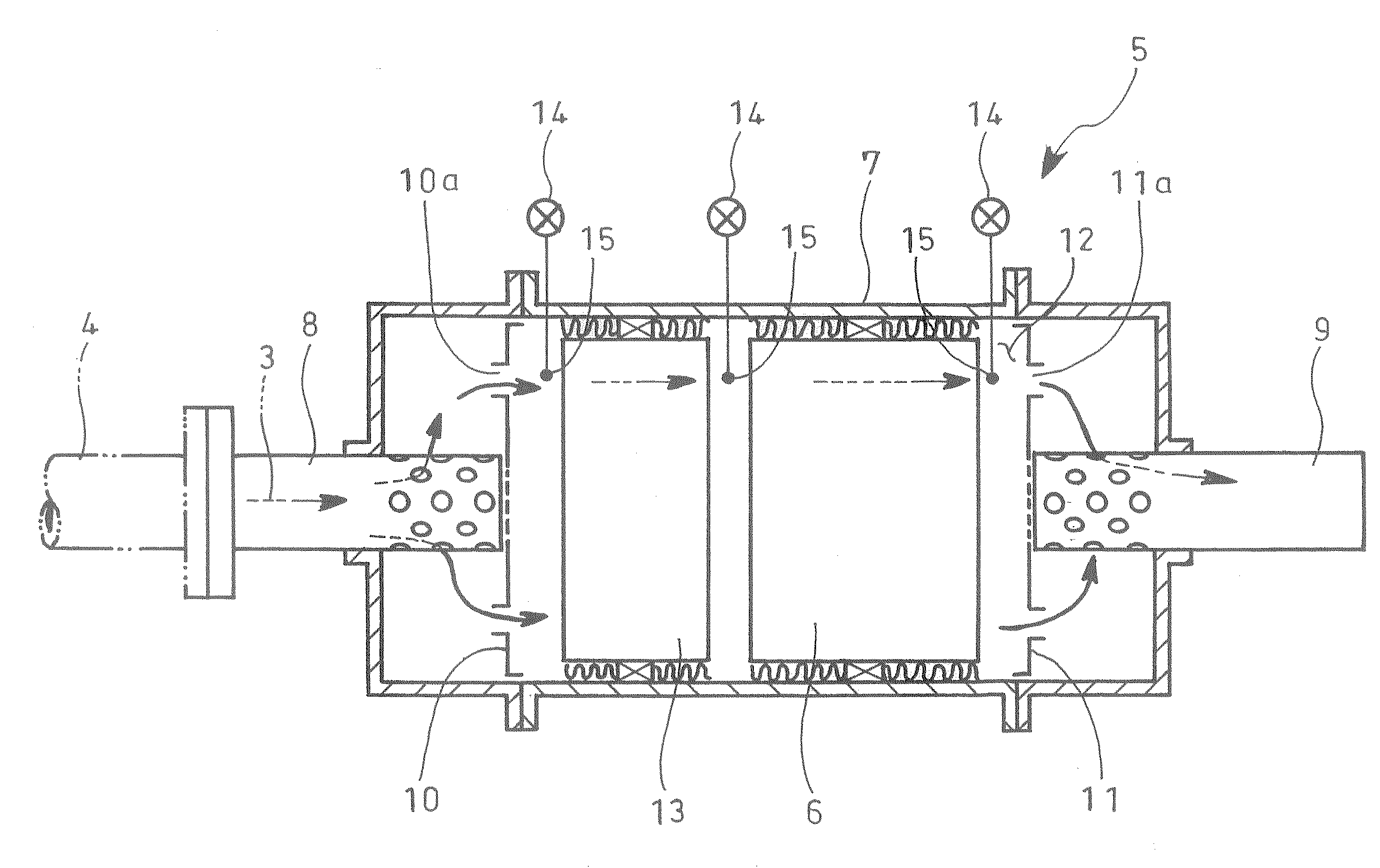
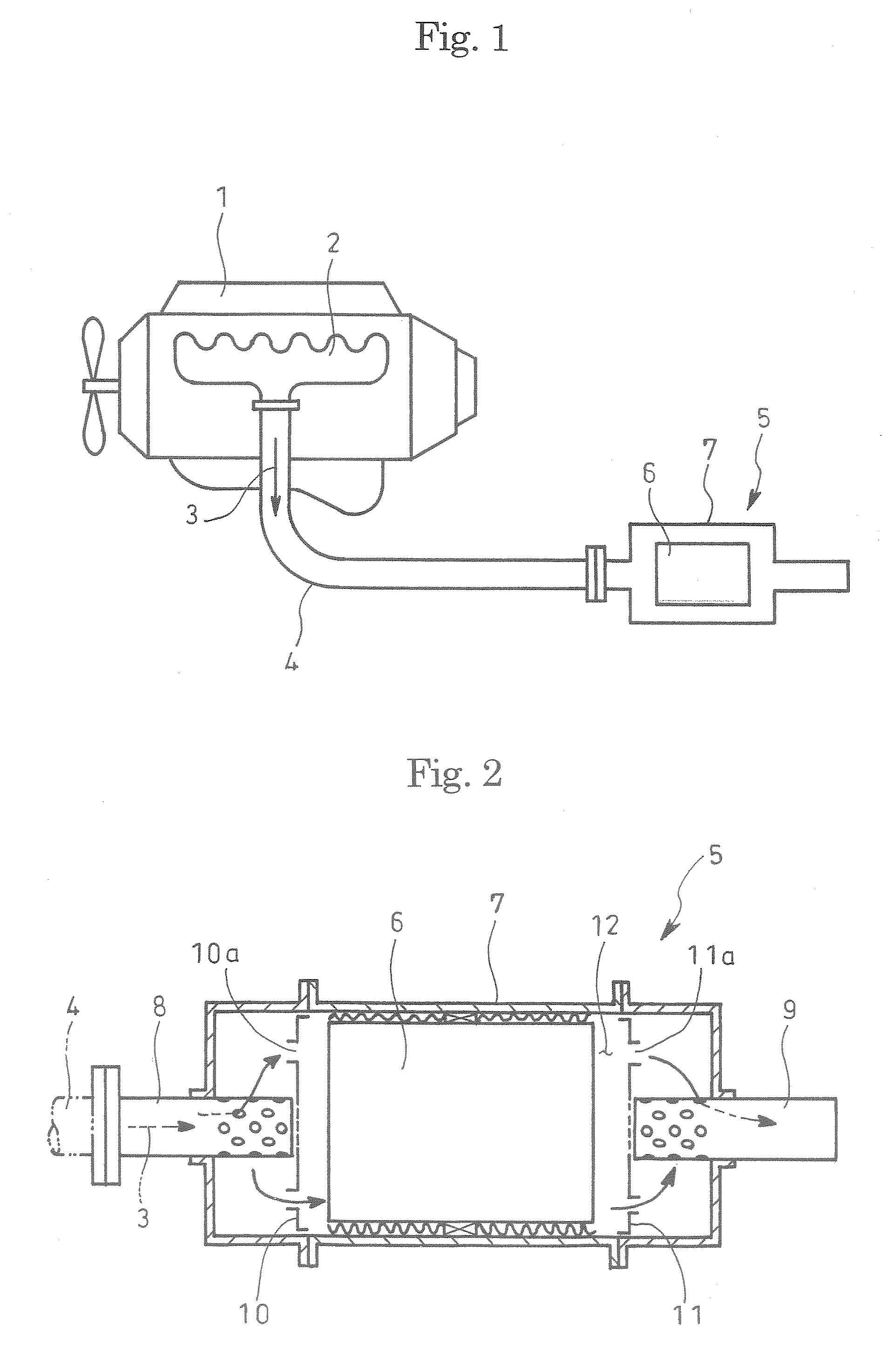
[0023]As shown in FIG. 7, in the embodiment, a pair of dispersion plates 10 and 11 with a number of communicating holes 10a and 11a, respectively, are arranged in a filter casing 7 incorporated in an exhaust pipe 4 such that the dispersion plates are opposed to each other in a direction of flows of the exhaust gas 3, catalytic regenerative particulate filter 6 being received in a reception chamber 12 defined by and between the dispersion plates 10 and 11, oxidation catalyst 13 being arranged in the reception chamber 12 and upstream of the particulate filter 6. A sensing element of the temperature sensor 14 is arranged in each of a position within the reception chamber 12 and adjacent to the inlet-side dispersion plate 10, a position within the reception chamber 12 and adjacent to the outlet-side dispersion plate 11 and a position between ...

embodiment 2

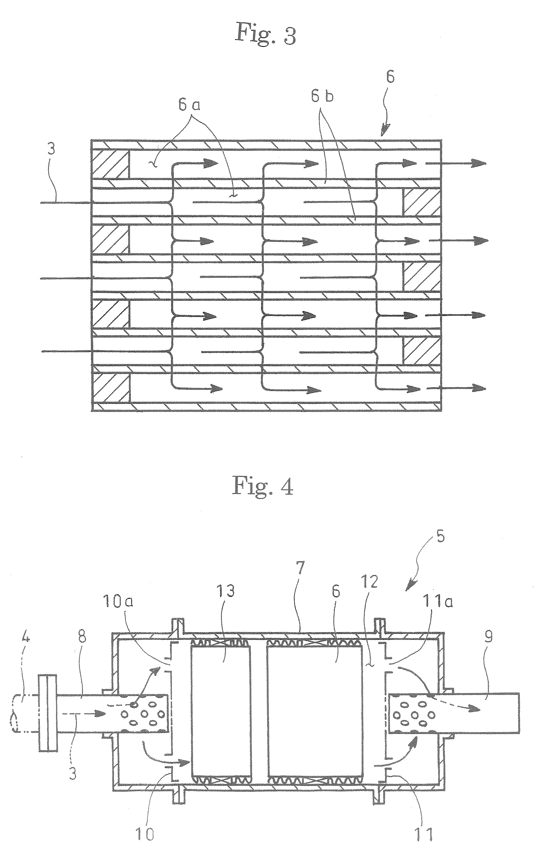
[0029]FIG. 9 shows a further embodiment applied to the dispersion plates of a type different from that shown in FIG. 8. The dispersion plates 10 and 11 shown have the inlet and exit pipes 8 and 9 arranged eccentrically due to layout relationship of the muffler 5 with surrounding structures, a number of relatively smaller-diameter communicating holes 10a and 11a being dispersed around connections to the pipes.

[0030]The temperature sensor 14 positioned in the reception chamber 12 and adjacent to the inlet-side dispersion plate 10 has the sensing element arranged just behind a relatively larger-diameter communicating hole 10a among the communicating holes 10a on the dispersion plate 10; similarly the temperature sensor 14 in the reception chamber 12 adjacent to the outlet-side dispersion plate 11 has the sensing element 15 just in front of a relatively larger-diameter communicating hole 11a among the communicating holes 11a on the dispersion plate 11. Such embodiment applied to this ki...


PUM

PropertyMeasurementUnit
temperatureaaaaaaaaaa
soluble organic fractionaaaaaaaaaa
boilingaaaaaaaaaa

Abstract

Sensing accuracy of a temperature sensor is enhanced so as to accurately conduct regeneration control of a particulate filter.
Disclosed is an exhaust emission control device wherein a pair of dispersion plates 10 and 11 with a number of communicating holes 10a and 11a are arranged in a filter casing 7 incorporated in an exhaust pipe such that the plates are opposed to each other in a direction of flows of exhaust gas 3, catalytic regenerative particulate filter 6 being received in a reception chamber 12 defined by and between the dispersion plates 10 and 11. A temperature sensor 14 is arranged in the filter casing 7 so as to detect exhaust temperature in the reception chamber 12, a sensing element 15 of the temperature sensor 14 being adapted to be in one of flows of the exhaust gas 3.

Description

TECHNICAL FIELD[0001]The present invention relates to an exhaust emission control device.BACKGROUND ART[0002]Particulates or particulate matter from a diesel engine is mainly constituted by carbonic soot and a soluble organic fraction (SOF) of high-boiling hydrocarbon and contains a trace of sulfate (misty sulfuric acid fraction). In order to suppress such kind of particulates from being discharged to atmosphere, it has been carried out as shown in FIG. 1 that a particulate filter 6 is incorporated in an exhaust pipe 4 through which exhaust gas 3 from a diesel engine 1 flows.[0003]In the example shown, exhaust gas 3 discharged from an automobile's diesel engine 1 (internal combustion engine) via an exhaust manifold 2 flows through an exhaust pipe 4 with a muffler 5 which receives therein catalytic regenerative particulate filter 6 integrally carrying oxidation catalyst, the particulate filter 6 being encased by a filter casing 7 which forms an outer cylinder of the muffler 5.[0004]M...

Claims


Application Information

Patent Timeline
Patent Type & Authority Applications(United States)
IPC IPC(8): F01N3/20F01N3/022G01K7/00B01D46/00B01D46/24B01D46/42B01D46/44B01D53/94F01N3/02F01N3/021F01N3/033F01N3/035F02D35/00
CPCB01D46/0061B01D46/2418B01D46/2451B01D46/448B01D53/94F01N13/0097F01N3/0335F01N3/035F01N13/008F01N2560/06F01N3/021B01D46/82
Inventor MATSUNAMI, MUNETOMOFUNABASHI, HIROSHI
Owner HINO MOTORS LTD
Why Eureka
Try Eureka