Process for Treating a Loaded Solvent Stream Having a Time-Varying Concentration of Contaminant

a technology of contaminant concentration and processing unit, which is applied in the direction of liquid degasification, separation process, dispersed particle separation, etc., can solve the problems of ensuring measures, and achieve the effect of reducing the concentration of time-varying contaminan

Inactive Publication Date: 2008-09-25
SHELL OIL CO
View PDF16 Cites 5 Cited by
  • Summary
  • Abstract
  • Description
  • Claims
  • Application Information

AI Technical Summary

Benefits of technology

[0006]To this end, the invention provides a process for treating a loaded solvent stream having a time-varying contaminant concentration, the process comprising the steps of: (a) providing a plurality of hold-up tanks; (b) feeding the loaded solvent stream in dependence on its contaminant concentration to one or more of the hold-up tanks and; (c) allowing loaded solvent stream to flow from the plurality of hold-up tanks to obtain a smoothed loaded solvent stream having a reduced time-varying contaminant concentration.
[0009]The use of a plurality of hold-up tanks instead of for example a single stirred tank offers advantages. In a single stirred tank, the loaded solvent would be collected and stirred in the hold-up tank. A problem arising when using a single stirred tank is that measures have to be taken to ensure that the whole tank is stirred to achieve a homogeneous concentration of the contaminant.
[0011]The process and unit according to the invention ensure that the final outlet flow from the plurality of hold-up tanks, which is the combined stream from the first and the second outlet streams, has a reduced time-varying contaminant concentration.

Problems solved by technology

A problem arising when using a single stirred tank is that measures have to be taken to ensure that the whole tank is stirred to achieve a homogeneous concentration of the contaminant.

Method used


Image

  • Process for Treating a Loaded Solvent Stream Having a Time-Varying Concentration of Contaminant
  • Process for Treating a Loaded Solvent Stream Having a Time-Varying Concentration of Contaminant

Examples


Embodiment Construction

[0012]Smoothing of time-varying contaminant concentration in loaded solvent streams is desirable for optimum operation of a contaminant removal unit, wherein contaminants are removed from the loaded solvent stream.

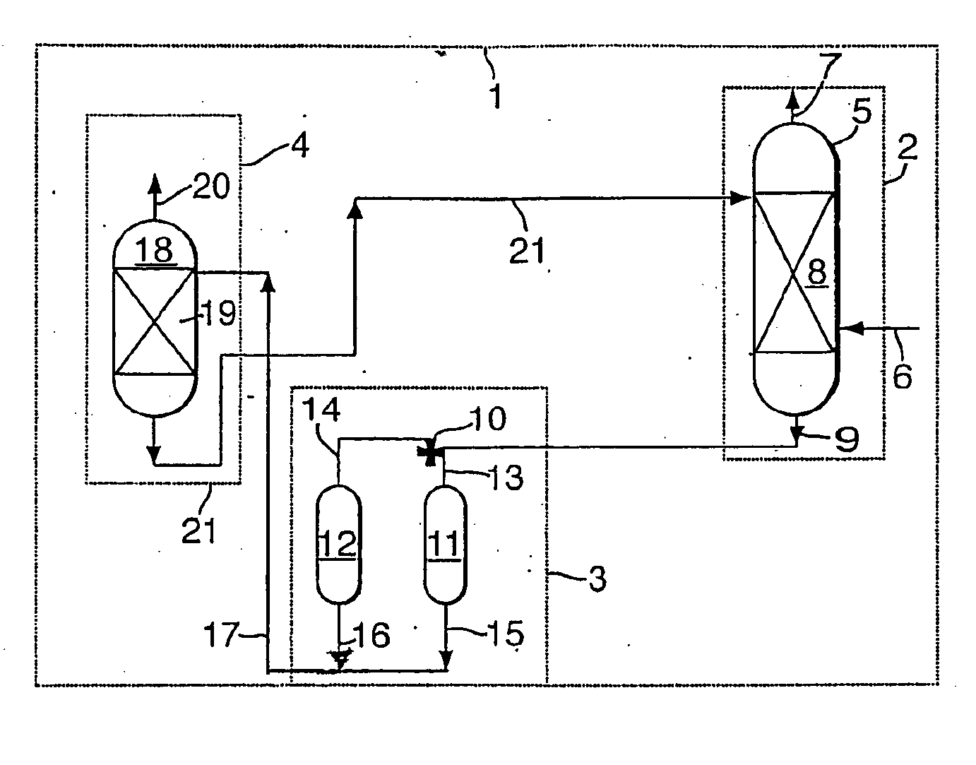
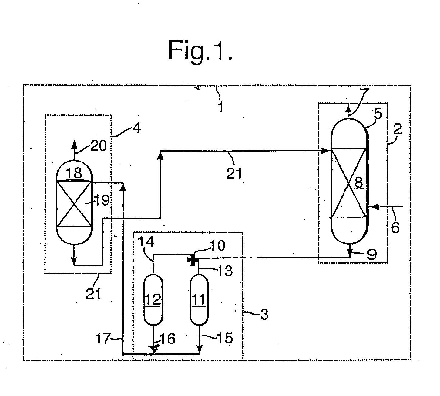
[0013]A particular situation is when a loaded solvent stream is derived from an upstream unit for removal of contaminants from a gas stream. This situation occurs for example in a gas treating unit wherein contaminants, especially sulphur contaminants such as mercaptans and / or hydrogen sulphide, are removed from a loaded gas stream in an upstream unit comprising at least one adsorbent bed. In the case where the upstream unit comprises two beds, one bed will be in adsorption mode (meaning that the operating conditions of the bed are such that contaminant adsorption from the loaded gas stream onto the bed will take place), while the other bed is in regeneration mode (meaning that the operating conditions of the bed are such that contaminant desorption will take place from th...


PUM

PropertyMeasurementUnit
temperaturesaaaaaaaaaa

Abstract

The invention provides a process for treating a loaded solvent stream having a time-varying contaminant concentration, the process comprising the steps of: (a) providing a plurality of hold-up tanks; (h) feeding the loaded solvent stream in dependence on its contaminant concentration to one or more of the hold-up tanks and; (c) allowing lowed solvent to flow from the plurality of hold-up tanks to obtain a smoothed loaded solvent stream having a reduced time-varying contaminant concentration. The invention further provides a treating unit comprising a circuit for circulating a solvent stream, which circuit includes a device for smoothing contaminant peak concentrations, said device comprising a plurality of hold-up tanks each hold-up tank having at least one inlet and an outlet equipped with an outlet valve, the device further comprising an inlet distributor allowing the control of solvent flow to one or more of the hold-up tanks.

Description

FIELD OF THE INVENTION[0001]The invention relates to a process and treating unit for treating a loaded solvent stream having a time-varying concentration of a contaminant.BACKGROUND OF THE INVENTION[0002]Loaded solvent streams can be obtained from processes for removing contaminants such as acidic compounds from a gas stream by washing the gas stream with fresh solvent. The use of solvents for removing contaminants such as acidic gasses is well known, see for instance the books A. L. Kohl and F. C. Riesenfeld, 1974, Gas Purification, 2nd edition, Gulf Publishing Co. Houston and R. N. Maddox, 1974, Gas and Liquid Sweetening, Campbell Petroleum Series.[0003]Preferably, a regenerable solvent is used in a continuous process.[0004]Generally, loaded solvent streams are treated by removing the contaminant and regenerating the solvent The removal of the contaminant from the loaded solvent stream can be effected for example by contacting the loaded solvent stream with a suitable stripping ag...

Claims


Application Information

Patent Timeline
Patent Type & Authority Applications(United States)
IPC IPC(8): B01D47/00B01D53/14
CPCB01D53/1425B01D53/1412
Inventor CARLSSON, ANDERSVAN HEERINGEN, GIJSBERT JANLAST, THIJME
Owner SHELL OIL CO
Why Eureka
Try Eureka