

Lighted Valance
a lighted valance and light source technology, applied in the field of valances, can solve the problems of non-uniform lighting effect, bulky and heavy lighted valances, and low light intensity, and achieve the effects of reducing long-term maintenance and replacement costs, reducing labor intensity, and being easy to manipulate during installation
- Summary
- Abstract
- Description
- Claims
- Application Information
AI Technical Summary
Benefits of technology
Problems solved by technology
Method used
Image

Examples
Embodiment Construction
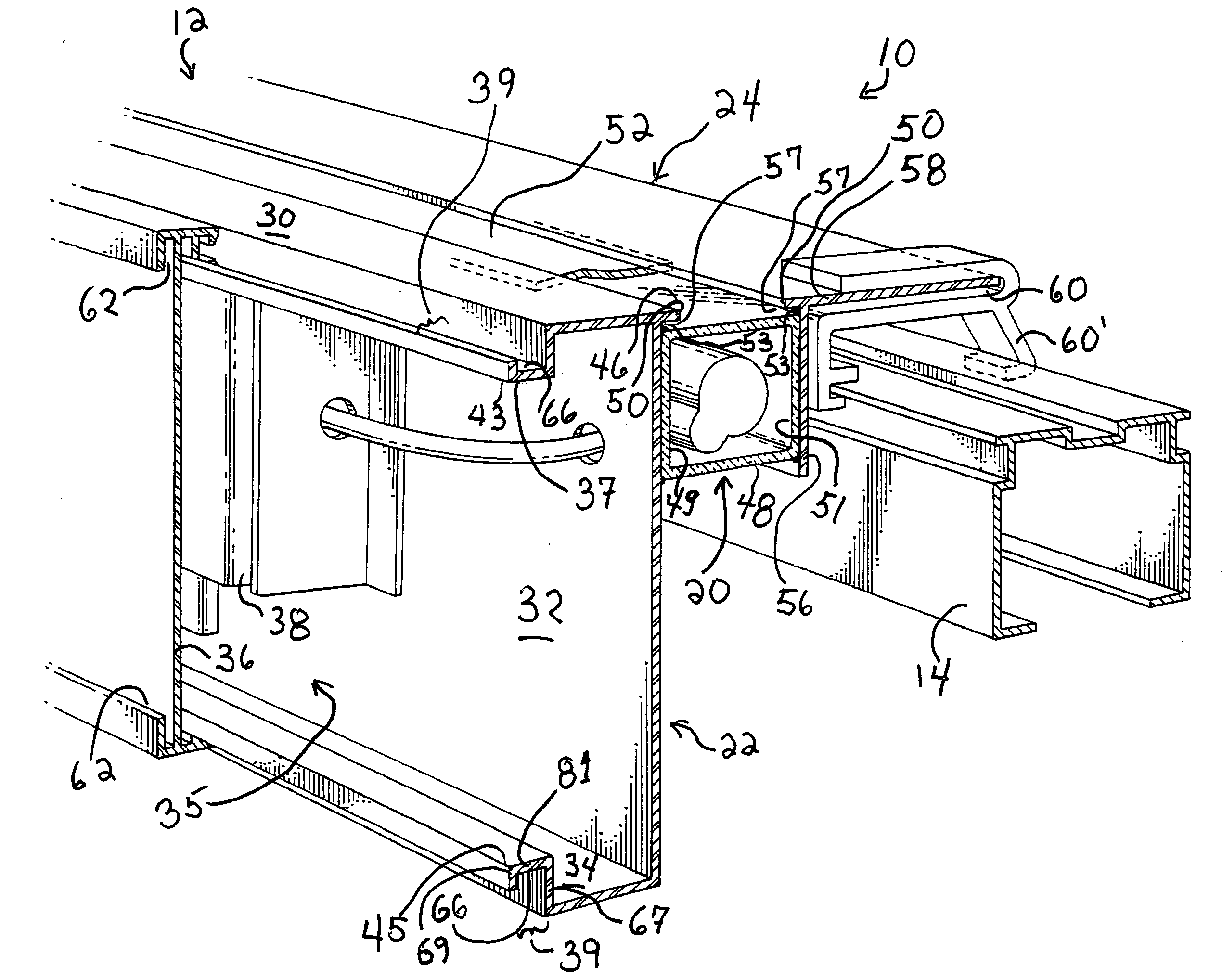
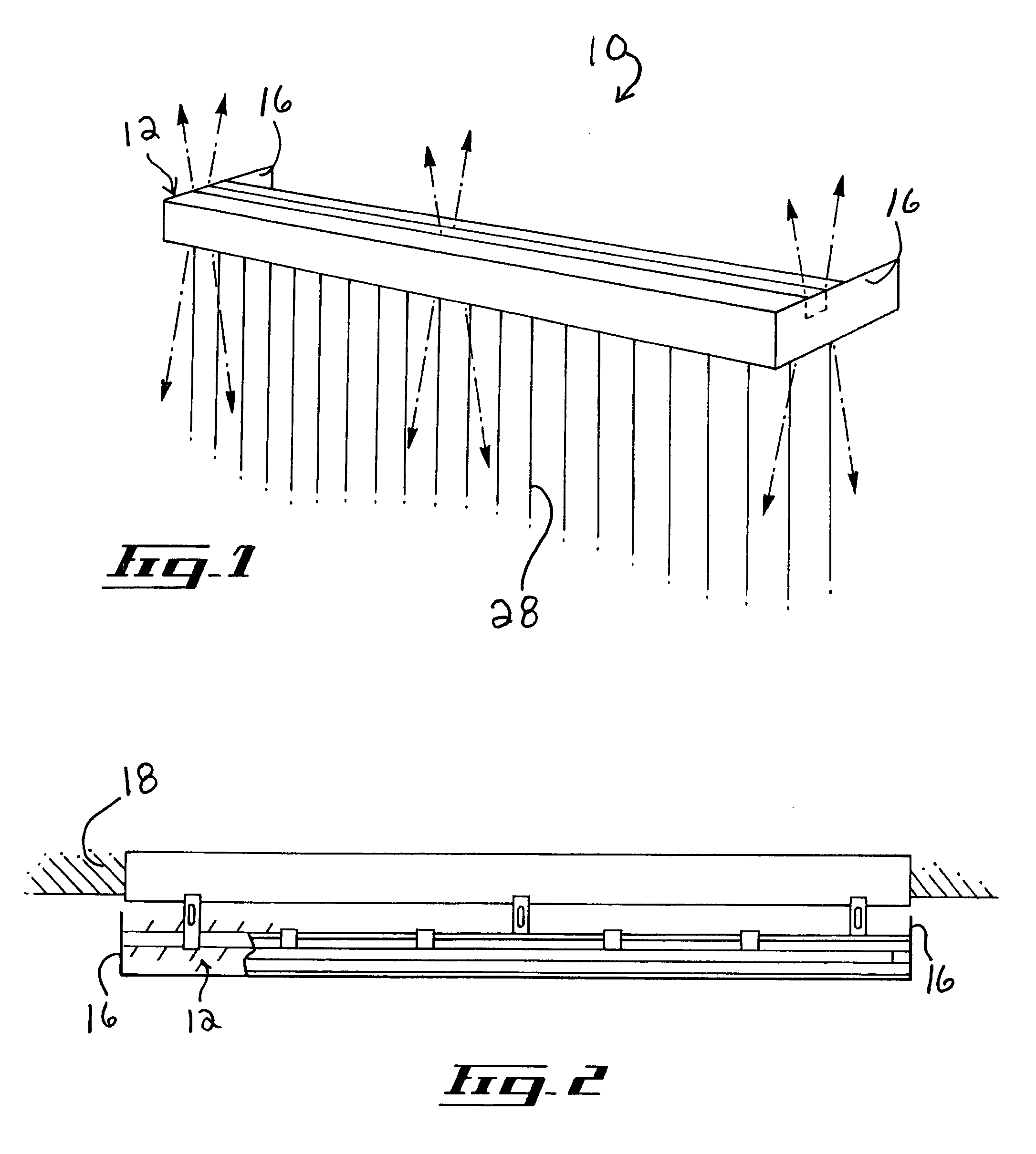
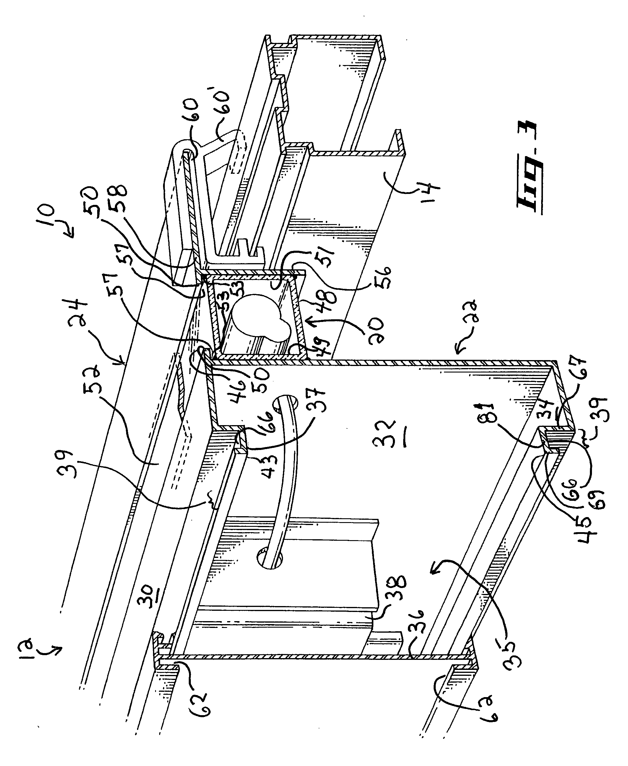
[0040]FIGS. 1 to 4 show various aspects of an embodiment of a valance 10 usable for concealing a headrail 14 having dependent mechanism and vertical blinds 28 (as best shown in FIG. 4) in accordance with an embodiment of the present invention. As best illustrated in FIG. 1, the valance 10 generally consists of an horizontally elongated main housing 12 which substantially extends the width of a headrail 14 and is terminated at each lateral ends with end walls 16 that are perpendicularly projecting towards a bearing wall 18 (as best shown in FIG. 2). The headrail 14 is affixed to the bearing wall 18 using conventional hooks 15, as shown in FIG. 4. The reader skilled in the art will readily appreciate that directional terminology, such as “up” and “top”, among others, is used in the present document to facilitate the description of the valance 10 and refers to a valance 10 mounted in a conventional orientation to the headrail 14. However, this directional terminology is used for clarit...
PUM
 Abstract
Description
Claims
Application Information