
Top drive washpipe system

Inactive Publication Date: 2008-09-25
NAT OILWELL VARCO LP
View PDF56 Cites 13 Cited by
  • Summary
  • Abstract
  • Description
  • Claims
  • Application Information

AI Technical Summary

Benefits of technology

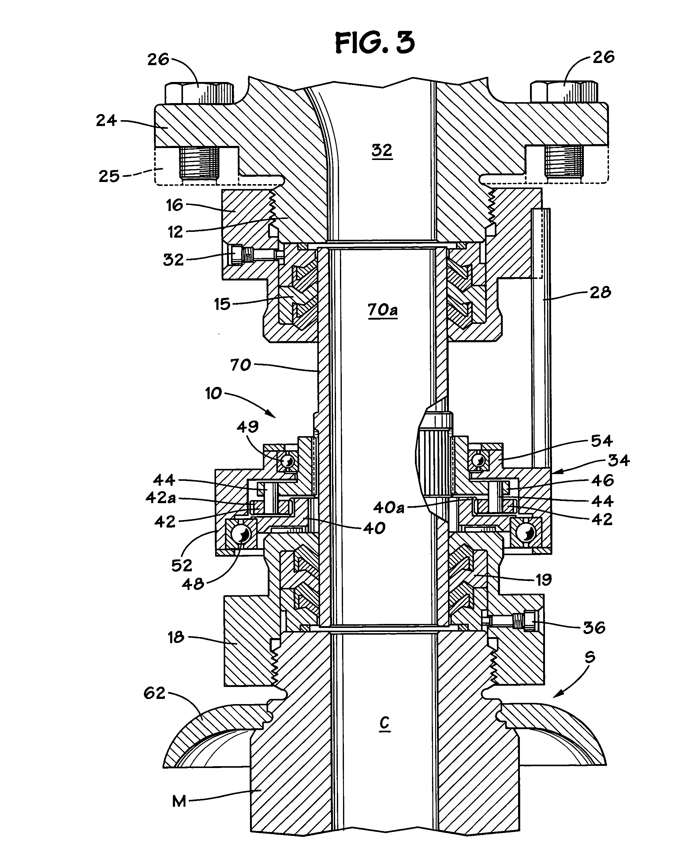
[0008]The present invention, in certain aspects, provides a shaft sealing assembly in which an auxiliary shaft rotated by a rotating main shaft is connected to and rotates with the shaft via a speed reducer, e.g., a gear drive apparatus, between the main shaft and the auxiliary shaft so that the auxiliary shaft rotates at a reduced speed compared to the speed of the main shaft, e.g. about one-half the main shaft speed, thus exposing seals dynamically sealing against the auxiliary shaft to a surface which is moving at the reduced speed, thus enhancing seal life.
[0010]The present invention discloses, in certain embodiments, a top drive system with a drive motor; a drive quill or main shaft; a gear system coupled to the drive motor; a top drive support system for supporting various items; and a washpipe shaft according to the present invention connected with the top drive main shaft via a speed reducer for rotation at a speed less than that of the main shaft to enhance the life of seal assemblies, e.g. with packings used to seal against the washpipe shaft.

Problems solved by technology

Due to the high pressures and surface speeds involved in this arrangement, service life of the washpipe packing is limited.
Drilling fluid leaks are therefore common on many drilling rigs, causing contamination and damage to associated components and environmental disruption.

Method used


Image

  • Top drive washpipe system
  • Top drive washpipe system
  • Top drive washpipe system

Examples


Embodiment Construction

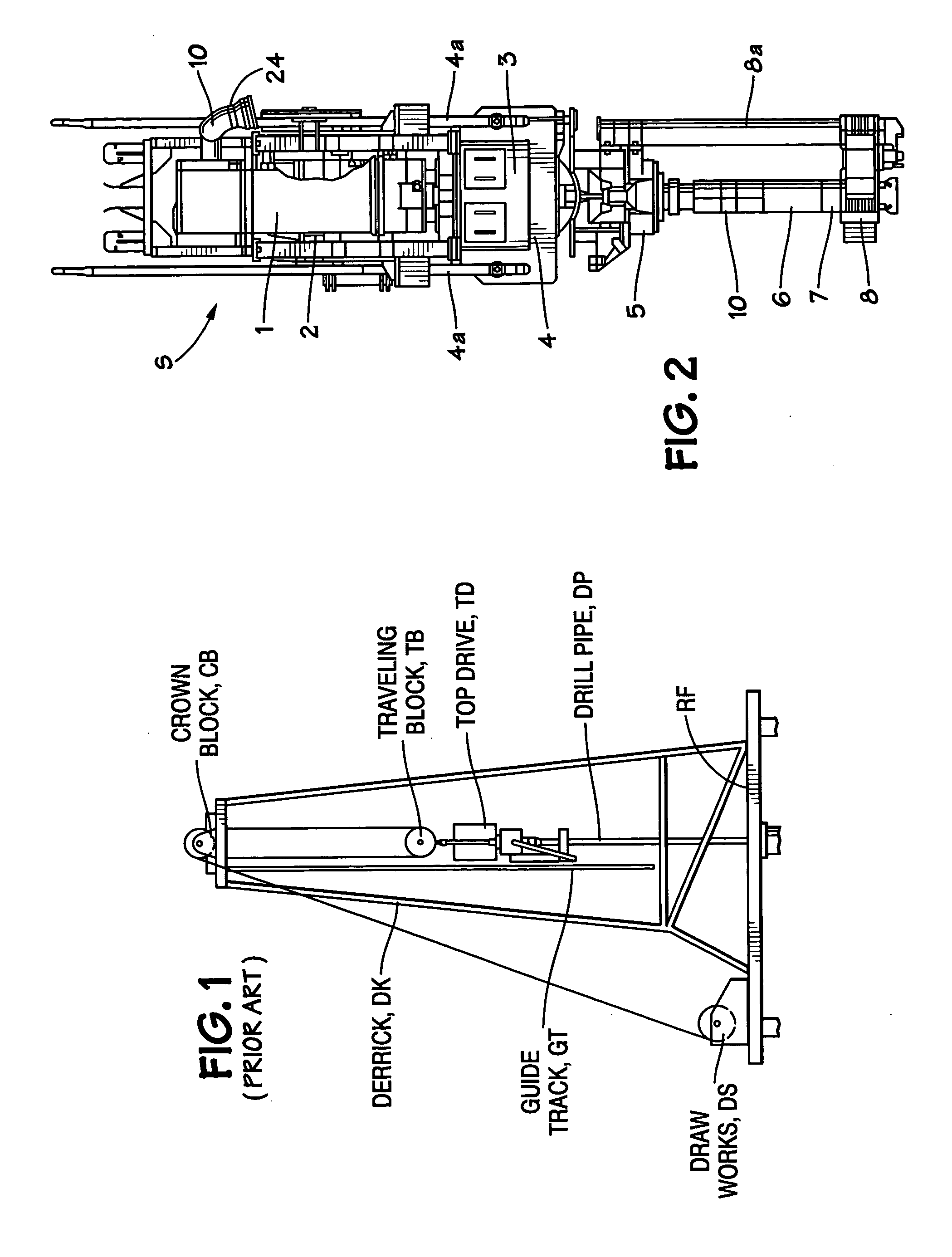
[0027]FIG. 1 shows a typical prior art drilling system with a derrick DK supporting a top drive TD which rotates drill pipe DP. The top drive is supported from a travelling block TB beneath a crown block CB. A drawworks, DS, on a rig floor RF raises and lowers the top drive. The top drive moves on a guide track GT.

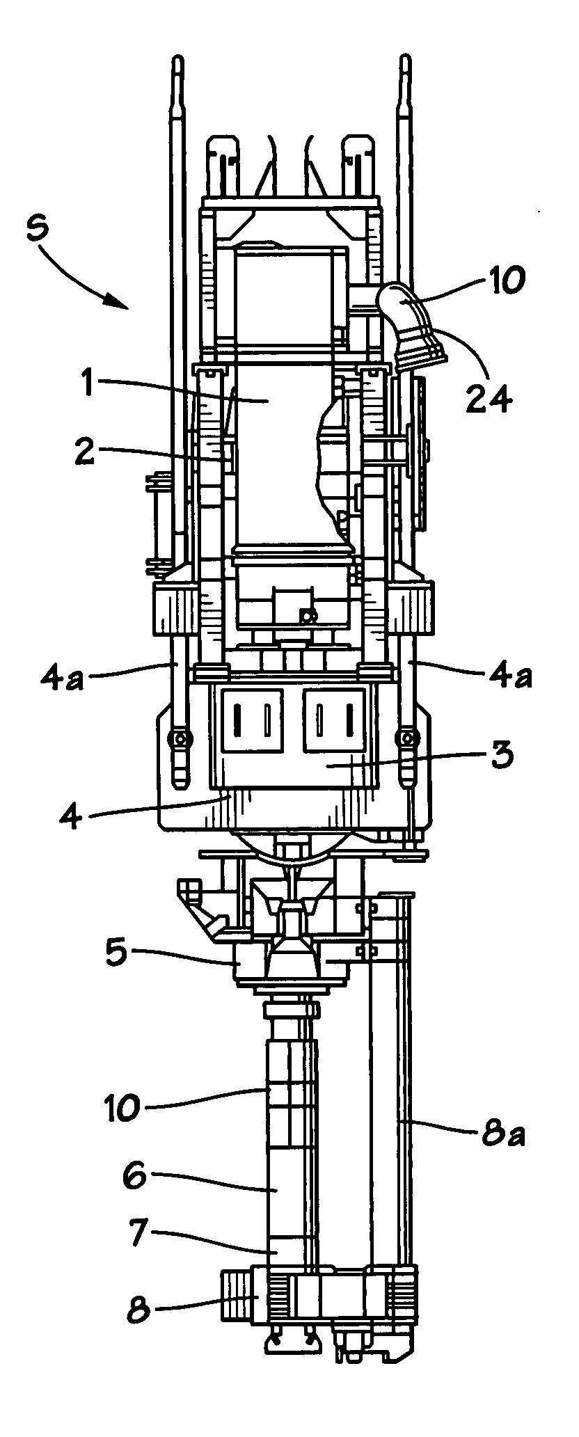
[0028]FIG. 2 shows a system S according to the present invention with a top drive 1 with a drive motor 2; a gear system 3 coupled to the top drive 1 with a bearing support 4 and support links 4a; a washpipe apparatus 10 with a washpipe shaft according to the present invention; an elevator load ring 5; a mud saver system 9; a lower internal blowout preventer 6; a saver sub 7; a gooseneck 24; and a pipe gripper 8 with supports 8A connected to the elevator load ring 5.

[0029]The present inventors have recognized the problems associated with the rotation of a shaft with respect to packing or seals and have realized that effective reduction of the speed of shaft rotation can enh...


PUM


Abstract

A top drive system for wellbore operations, the top drive system, in at least certain aspects, including a motor, a main shaft driven by the motor, the main shaft having a top end and a bottom end, a speed reduction system interconnected with the main shaft, a washpipe shaft interconnected with the speed reduction system for driving the washpipe shaft at a speed of rotation less than a speed of rotation of the main shaft. This abstract is provided to comply with the rules requiring an abstract which will allow a searcher or other reader to quickly ascertain the subject matter of the technical disclosure and is submitted with the understanding that it will not be used to interpret or limit the scope or meaning of the claims, 37 C.P.R. 1.72(b).

Description

CROSS-REFERENCE TO RELATED APPLICATION[0001]The present invention and the application for this patent claim priority under the U.S. Patent law §120 of U.S. Application Ser. No. 60 / 902,798 filed Feb. 22, 2007.BACKGROUND OF THE INVENTION[0002]1. Field of the Invention[0003]This invention is directed to wellbore drilling top drive systems; to washpipe apparatuses for such systems; and to sealing systems for rotating members.[0004]2. Description of Related Art[0005]Drilling fluids are transmitted to drilling swivels and top drive drilling systems through a high-pressure swivel apparatus known as a “washpipe” with a seal known as a “washpipe packing” assembly. This packing assembly consists of a tubular component which is held stationary, and through which the drilling fluid flows under high pressure. A rotating seal assembly of contact lip seals is mechanically fixed to and rotates with the main shaft of the top drive or swivel, and forms a dynamic seal against the outer surface of the ...

Claims


Application Information

Patent Timeline
IPC IPC(8): E21B3/00
CPCE21B33/02E21B21/02
Inventor STUBSTAD, SVEIN
Owner NAT OILWELL VARCO LP
Learn More