Offset drive system for utility vehicles

a technology for utility vehicles and drive systems, applied in the direction of driving chains, electric propulsion mountings, electric devices, etc., can solve the problems of engine slippage and drive train slippage, and achieve the effect of efficient torque production and efficient use of spa

Active Publication Date: 2008-09-25
FAIRFIELD MFG CO INC
View PDF99 Cites 42 Cited by
  • Summary
  • Abstract
  • Description
  • Claims
  • Application Information

AI Technical Summary

Benefits of technology

[0030]It is an object of the present invention to provide offset planetary gear reducers for use in combination with high speed motors for efficient use of space in a utility vehicle.
[0031]It is an ob...

Problems solved by technology

Additionally, some slippage of the engine with resp...

Method used


Image

  • Offset drive system for utility vehicles
  • Offset drive system for utility vehicles
  • Offset drive system for utility vehicles

Examples


Embodiment Construction

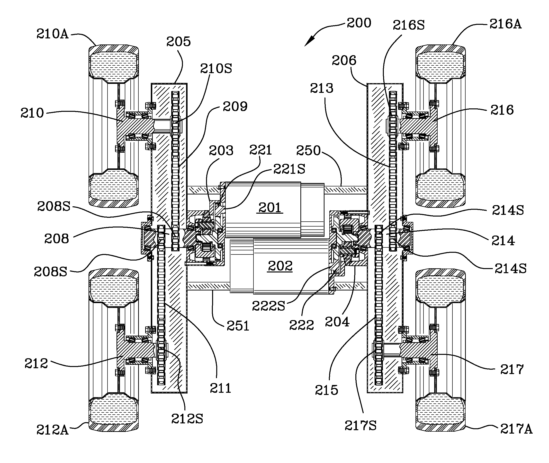
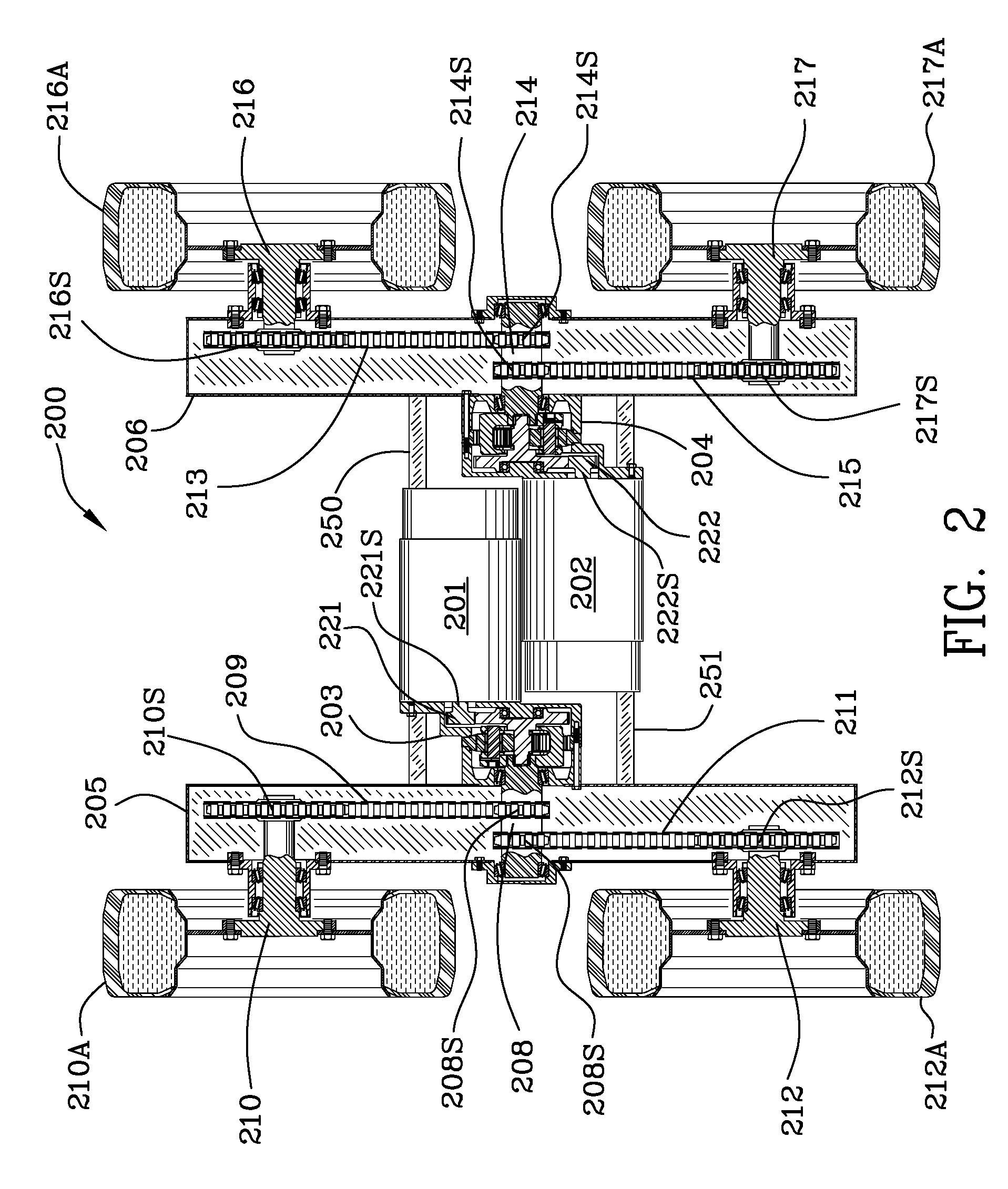
[0042]FIG. 2 is a top plan view 200 of the utility vehicle illustrating two alternating current electric motors 201, 202 oriented side by side with each having an offset planetary gear reducer 203, 204 driving a respective output shaft 208, 214. Although reference numerals 201, 202 refer to high speed alternating current electric motors, it is specifically contemplated that other high speed motor types may be used such as direct current motors, hydraulic motors and pneumatic motors.

[0043]The utility vehicle includes a frame 205, 206, 250, 251 for supporting vehicle components. As illustrated in FIG. 2, side frame member 205 is on the left hand side of the vehicle and side frame member 206 is on the right hand side of the utility vehicle. The two side frame members 205, 206 are shown in section in FIG. 2, FIG. 2A, and FIG. 2B.

[0044]Frame side member 205 supports first chain driven wheel shaft 210. Sprocket 210S is formed as part of the wheel shaft 210 or alternatively is a separate s...


PUM


Abstract

A wheel driven utility vehicle includes a frame and two small volume high speed alternating current electric motors arranged side by side for driving the vehicle. Alternatively high speed direct current, hydraulic or pneumatic direct current motors may be used with suitable controls. Each motor has an output shaft which drives an offset planetary gear reducer. Each offset planetary gear reducer is affixed to the electric motor and includes an output carrier interconnected with an output shaft. Each output shaft includes first and second chain drive sprockets which drive chains interconnected with shafts driving the front and rear wheels respectively. Each offset planetary gear reducer enables use of space saving high speed relatively low-torque alternating current electric motors with attendant large speed reductions. Gear reduction enables the production of sufficient torque at the wheels of the vehicle. Applications in addition to utility vehicles are also specifically contemplated.

Description

FIELD OF THE INVENTION[0001]The invention is in the field of offset drive systems for utility vehicles. In particular, this invention is in the field of utility vehicles (such as Skid-Steer(g and Bobcat® vehicles), fork lifts and front end loader machines.BACKGROUND OF THE INVENTION[0002]Traditionally, Skid-Steer® Loader Machines as made famous by manufacturers such as Bobcat® and the like have been powered almost exclusively by hydraulics. Skid-Steer® is a registered trademark of Arts-way Manufacturing Co., Inc., a Delaware Corporation. Bobcat® is a registered trademark of Clark Equipment Company of New Jersey.[0003]These machines traditionally have gasoline or diesel internal combustion engines that drive a hydraulic pump. The pump usually provides power to two independently controlled hydraulic motors one for each side of the machine. The output of each motor drives a drive sprocket with two sets of sprocket teeth. One set of sprocket teeth drives a chain that goes to a front whe...

Claims


Application Information

Patent Timeline
IPC IPC(8): B62D11/00B66F9/00E02F9/16
CPCB60K1/02B60K7/0007B60K7/0015B60K17/36B60K2001/001B60K17/342B62D11/04B66F9/07572E02F9/02E02F9/207B60Y2200/41B60L2200/40B60L2220/50Y02T10/64Y02P90/60
Inventor SCHOON, BENJAMIN WARREN
Owner FAIRFIELD MFG CO INC
Why Eureka
Try Eureka