
Surgical data carrier

a data carrier and surgical technology, applied in the field of surgical data carriers, can solve the problems of difficult grasp by users, relative movement of data carriers and implants, etc., and achieve the effect of reducing the risk of infection for patients as a result of data carriers remaining in the body, and reducing the risk of infection for patients

Inactive Publication Date: 2008-09-25
AESCULAP AG
View PDF20 Cites 159 Cited by
  • Summary
  • Abstract
  • Description
  • Claims
  • Application Information

AI Technical Summary

Benefits of technology

[0008]It is possible for the user, by means of the actuating device, to carry out the transfer of the connecting device from a connecting position into a release position in a user-friendly and controllable manner. This improves the handling capability of the data carrier. Furthermore, the solution to the object according to the invention allows the user to intentionally delay the removal of the data carrier from the implant for such a time until the connecting device has taken up a release position. It is, therefore, possible for the user to control the taking up of the release position, i.e., the releasability of the data carrier. The risk of damage to the data carrier, which can occur, for example, when the data carrier is detached from the implant too quickly or in an inappropriate or uncontrolled manner, is consequently reduced.
[0051]It is favorable for the inexpensive production of the data carrier when the data carrier is designed in one piece. Preferably, it is produced, in particular, in one piece from a plastic material.

Problems solved by technology

In contrast thereto, it has proven to be disadvantageous when using the implantation system described in the cited publication U.S. Pat. No. 6,929,646 B2 that a relative movement of data carrier and implant can be accomplished only when pulling forces act on both the implant and the data carrier.
This is particularly disadvantageous in the case of implants which have small dimensions and are, therefore, difficult for the user to grasp.

Method used


Image

  • Surgical data carrier
  • Surgical data carrier
  • Surgical data carrier

Examples


Embodiment Construction

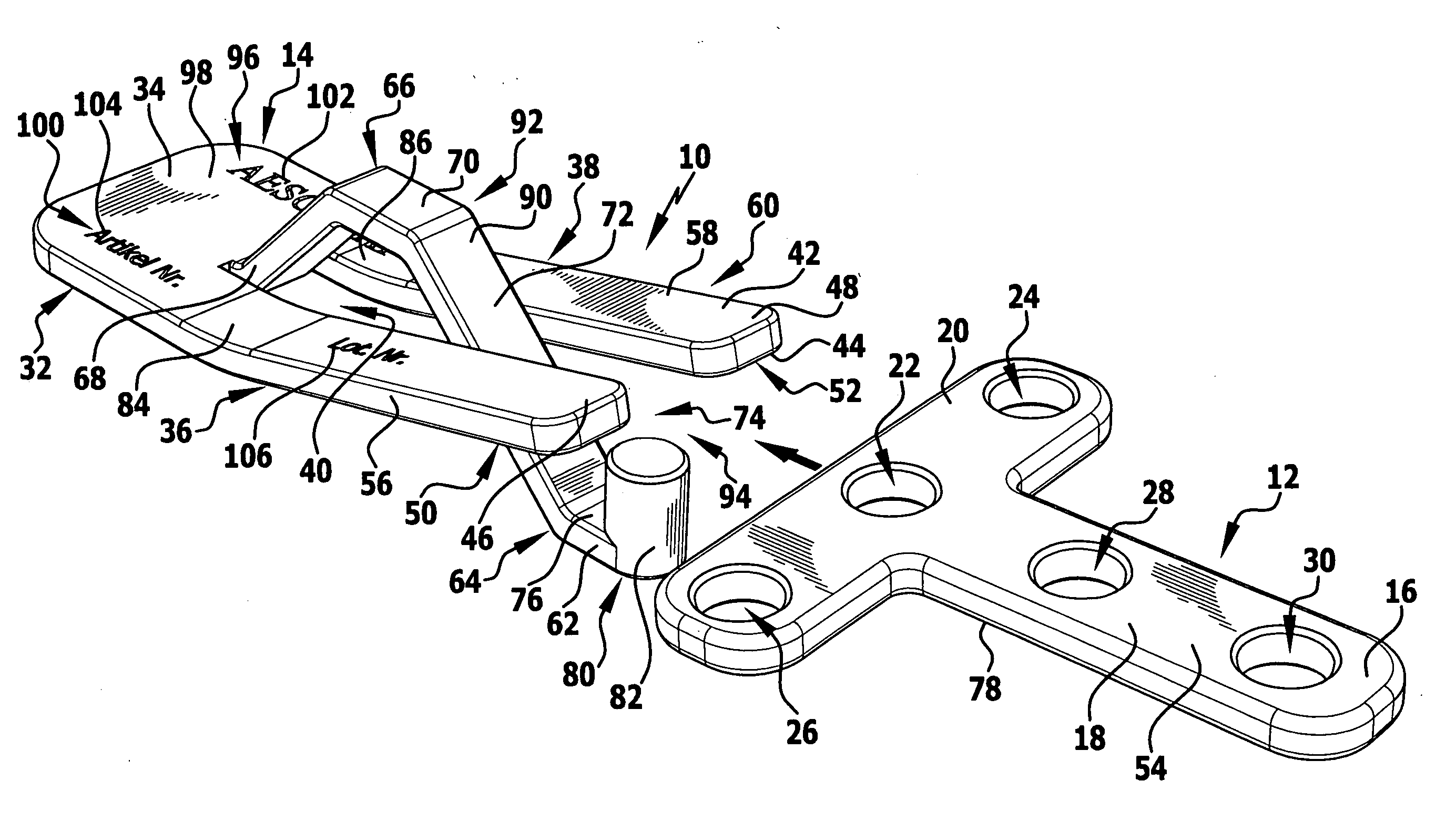
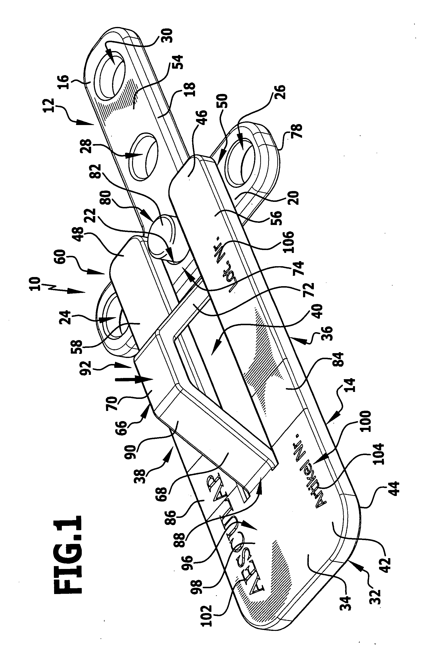
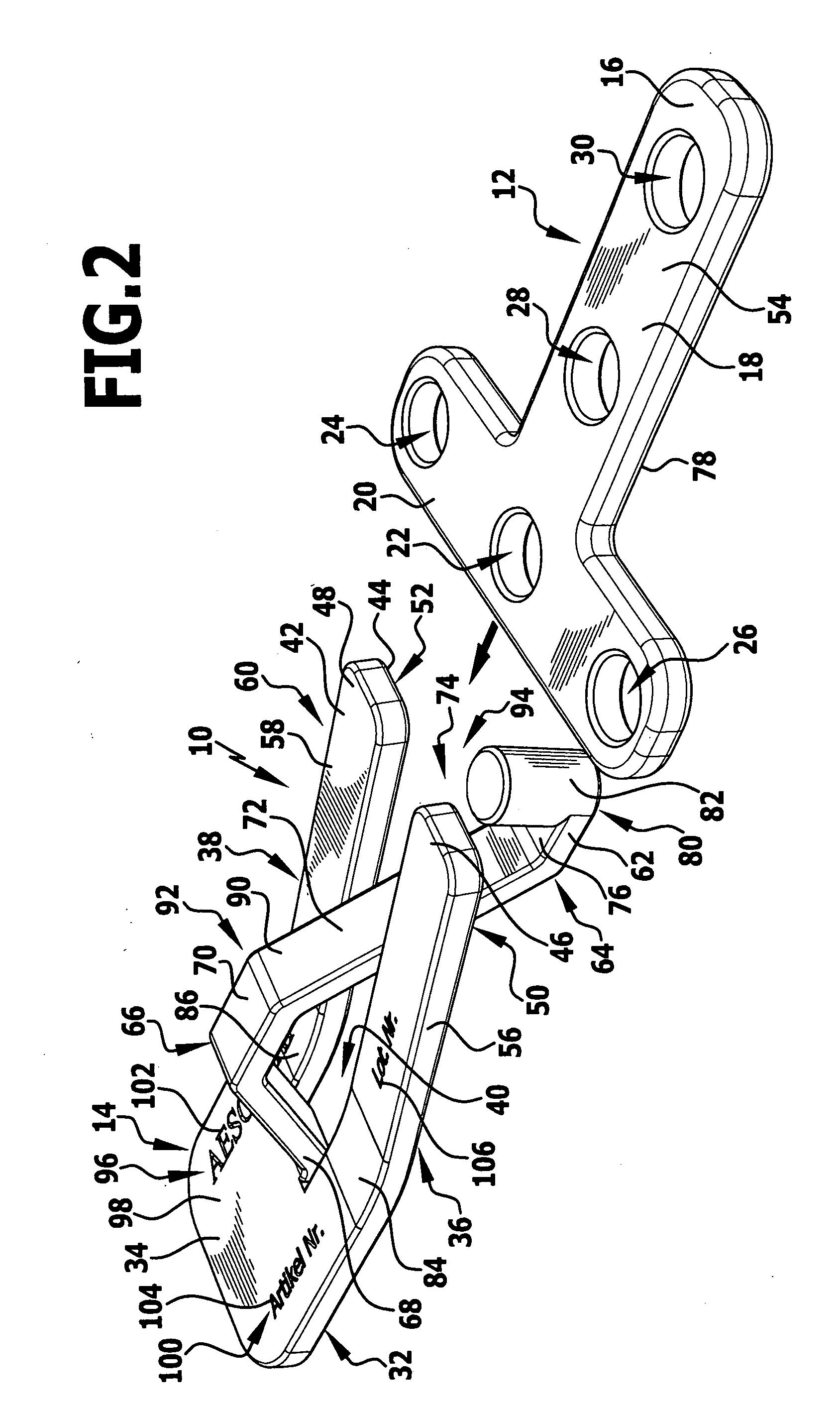
[0059]A preferred embodiment of an implantation system according to the invention is given the reference numeral 10 in the drawings. The implantation system 10 comprises a medical implant 12 as well as a preferred embodiment of a surgical data carrier 14 likewise according to the invention.

[0060]The implant 12 is designed as a surgical perforated plate 16 produced from titanium for the connection of bones and / or bone fragments. The perforated plate has the shape of a T with a longitudinal section 18 which corresponds to the long stroke of the T as well as with a transverse section 20 which is arranged at one end of the longitudinal section 18, is aligned at right angles to it and corresponds to the cross stroke of the T. A plurality of screw holes 22, 24, 26, 28 and 30 in the form of passages in the longitudinal section 18 and the transverse section 20 can have securing means which are not shown in the drawings, such as, for example, bone screws, passing through them in order to att...


PUM


Abstract

The invention relates to a surgical data carrier for the identification of a medical implant, in particular, a surgical plate for the fixing of bones or bone fragments, wherein the data carrier has a carrier element and a connecting device which comprises a receptacle for the insertion of at least part of the implant. In order to make such a surgical data carrier available which has an improved handling capability, it is suggested in accordance with the invention that the data carrier have an actuating device which can be actuated by a user and with which the connecting device can be transferred from a connecting position, in which the implant is held in the receptacle, into a release position, in which the data carrier can be detached from the implant. The invention relates, in addition, to a surgical implantation system.

Description

[0001]The present disclosure relates to the subject matter disclosed in German application number 10 2007 011 093.8 of Feb. 28, 2007, which is incorporated herein by reference in its entirety and for all purposes.BACKGROUND OF THE INVENTION[0002]The invention relates to a surgical data carrier for the identification of a medical implant, in particular, a surgical plate for the fixing of bones or bone fragments, wherein the data carrier has a carrier element and a connecting device which comprises a receptacle for the insertion of at least part of the implant.[0003]In addition, the invention relates to a surgical implantation system comprising at least one medical implant, in particular, a surgical plate for the fixing of bones or bone fragments and a surgical data carrier which can be detachably connected to the implant for the identification of the implant, wherein the data carrier has a carrier element and a connecting device which comprises a receptacle for the insertion of at le...

Claims


Application Information

Patent Timeline
Patent Type & Authority Applications(United States)
IPC IPC(8): B65D85/00A61B17/80
CPCA61B17/80A61B19/44A61B2017/00477A61B2019/4868A61B2019/446A61B2019/448A61B2019/442A61B90/90A61B90/94A61B90/96A61B90/98A61B2090/0813
Inventor PLEIL, THOMASNESPER, MARKUSSCHAUER, DIRKWEISSHAUPT, DIETER
Owner AESCULAP AG
Learn More