
Ventricle drain

a technology of ventricle and drain tube, which is applied in the direction of wound drains, intravenous devices, infusion needles, etc., can solve the problems of confused and motor hyperactive patients unintentionally removing the ventricular drain, and the principle of external csf draining is not ideal,

Inactive Publication Date: 2002-05-30
CSF DYNAMICS
View PDF2 Cites 4 Cited by
  • Summary
  • Abstract
  • Description
  • Claims
  • Application Information

AI Technical Summary

Benefits of technology

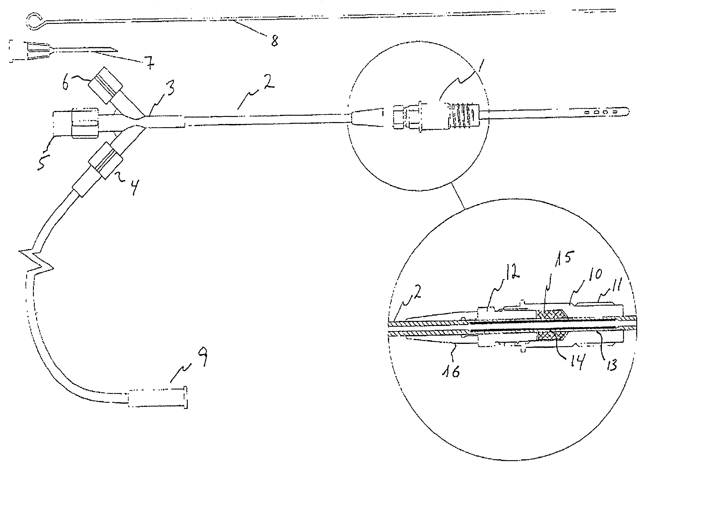
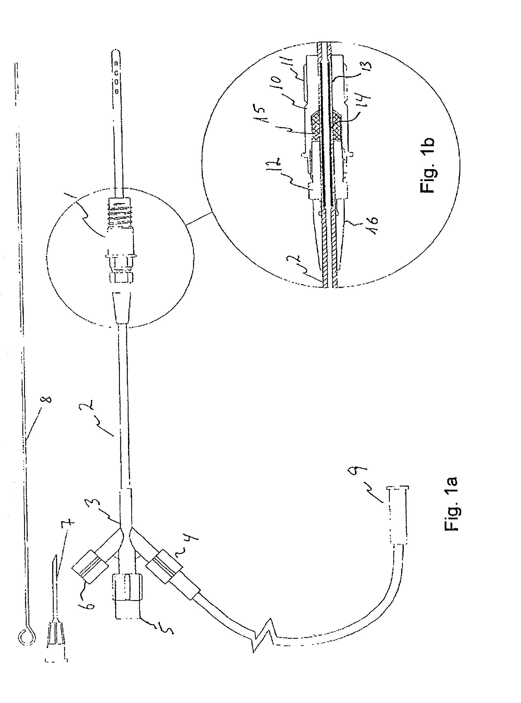
[0015] The invention thus provides means for passing a catheter through a sealed passage through a fixture attached to the aperture of the scull. The fixture could be attached to the scull as the aperture is drilled, e.g. when the treatment of the patient begins. The bone and skin tissue will grow into a sealing engagement with the fixture and since the fixture is not to be replaced, the risk of infections occurring between the fixture and the skull is low. By means of the fixture and the fastener, the catheter and / or the seal may be re-positioned or replaced repeatedly without interfering with the skin and bone tissue of the scull.
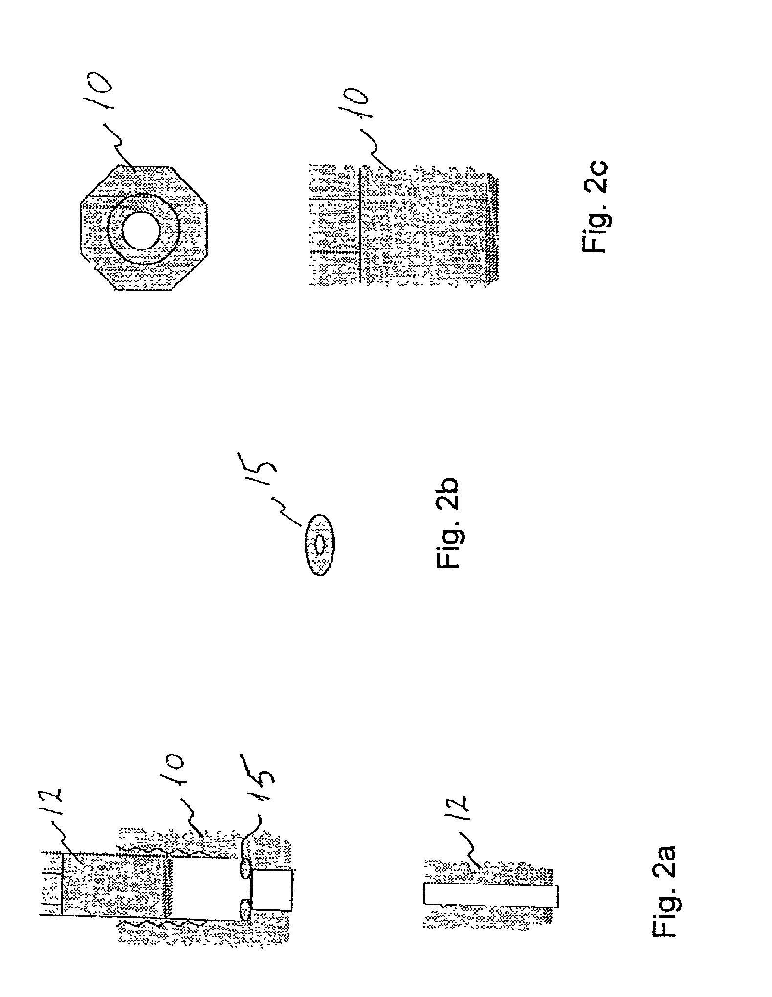
[0017] The fixture has a conduit or passage for passing the catheter through the skull. The passage could be divided into a proximal (lower) part and a distal (upper) part, the proximal part defining the inserted end of the fixture and thus being closest to the patient, when fitted in an aperture. If an intermediate part of the passage, between the proximal part and the distal part, is provided with a smaller radial size, the seal may be prevented from passing through the passage. According to one embodiment, the radial size of the proximal part of the passage is smaller than the radial size of the proximal part of the passage. Thereby, the transition between the proximal part and the distal part of the passage provides a seat for the seal. According to another embodiment, the passage is divided into a proximal part and a distal part by an intermediate part, which intermediate part being provided with a smaller radial size than at least the distal part and optionally also with a smaller radial size than the proximal part. The seat for the seal can also be established by inserting a locking washer into the passage. The passage could e.g. be provided with an internal circular groove for catching a washer. The division of the passage in two parts, either by use of a washer or by means of changing radial size of the passage, prevents the seal from moving down through the fixture and into the brain.
[0018] According to a preferred embodiment of the invention, the passage through the fixture is provided with two end parts and an intermediate part. The two end parts being provided with radial sizes which are larger than the radial size of the intermediate part. As an example the fixture may be constricted by the two end parts being provided with decreasing radial sizes towards the intermediate part of the passage. In that way, the catheter may easily be positioned with guiding means such as an introducer or stylet--e.g. a stiff needle--within a circular area defined by the limitations of the introducer and catheter to move in the passage. The wider the end portions are the better a manoeuvrability of the guiding means is achieved. When the catheter has been positioned in the brain, the guiding pin is removed and the fastener is attached for locking the catheter tightly to the fixture.

Problems solved by technology

Increased intracranial pressure, arise when the outflow of the CSF is obstructed, eventually leading to an increase in the amount of intracranially located cerebrospinal fluid.
Clinical experience has proven that this principle of external CSF draining is not an ideal solution.
The often confused and motor hyperactive patient unintentionally removes the ventricular drain by simply pulling it out of the scalp.
The drain can easily slide in and out through the cutaneous canal which increases the risk of infection.
Reinsertion of the ventricular drain through the same skin opening further increases the risk of infection.
While infection of the CSF in most cases can be treated by antibiotics, infection increases the length of the hospitalisation--typically in intensive care units--and adds morbidity following the initial disease.

Method used


Image

  • Ventricle drain
  • Ventricle drain
  • Ventricle drain

Examples


Embodiment Construction

[0007] An object of the present invention is to provide means by which access to the intracranial compartment is completely sealed from the skin and the scalp tissues which makes it possible to change the drain when necessary and without bringing the drain in contact with the scalp. It is a further object of the invention to provide an improved ventricle draining system supporting a better fixation of the drain to avoid the drain from sliding.

[0008] Accordingly, a first aspect of the present invention relates to a ventricle drain comprising:

[0009] sealing means for providing a sealed passage through an aperture in a cranial bone, and

[0010] a catheter having a free end and an end adapted for insertion into the aperture through the sealed passage for draining bodily fluids,

[0011] wherein the sealing means comprises

[0012] a fixture with a conduit defining a passage through the fixture, the fixture being provided with fastening means for attachment of the fixture to the aperture in the ...


PUM


Abstract

A ventricle drain includes a sealing structure for providing a sealed passage through an aperture in a cranial bone. The ventricle drain also includes a catheter having a free end and an end adapted for insertion into the aperture through the sealed passage for draining bodily fluids. The sealing structure includes a fixture with a conduit defining a passage through the fixture, a seal for sealed engagement with the catheter and the fixture, and a fastener for securing the catheter to the fixture. The fixture is provided with a fastening structure for attachment of the fixture to the aperture.

Description

[0001] The present invention relates to a cerebrospinal fluid draining system for draining cerebro-spinal fluid from the brain ventricles through a sealed passage in a scalp aperture.DESCRIPTION OF THE PRIOR ART[0002] External draining of cerebrospinal fluid (CSF) from the intracranial CSF compartments is a standard neuro-surgical method aiming at reducing increased intracranial pressure.[0003] CSF is formed in the ventricular system irrespective of the intracranial pressure (ICP). The formation rate is constant, with a range of 0.3-0.4 ml / min. (Borgesen and Glerris 1987). Increased intracranial pressure, arise when the outflow of the CSF is obstructed, eventually leading to an increase in the amount of intracranially located cerebrospinal fluid. The obstruction may be localised in the aqueduct or the IV ventricle or in the normal resorption sites in villi arachnoidales in connection with the sagittal sinus.[0004] Typically a passage is provided in the cranial bone, e.g. by means of...

Claims


Application Information

Patent Timeline
IPC IPC(8): A61M27/00
CPCA61M27/006
Inventor BORGESEN, SVEND ERIK
Owner CSF DYNAMICS
Learn More