Ultrasonic sensor and obstacle detection device

a technology of ultrasonic sensor and obstacle detection, which is applied in the direction of electrical transducers, mechanical vibration separation, instruments, etc., can solve the problems of reducing the rigidity of the vibrating plate, affecting reducing the detection accuracy of objects, so as to improve the detection area of objects, improve the design of sensors, and avoid the effect of reducing impact strength

Inactive Publication Date: 2008-09-25
DENSO CORP +1
View PDF0 Cites 47 Cited by
  • Summary
  • Abstract
  • Description
  • Claims
  • Application Information

AI Technical Summary

Benefits of technology

[0017]According to a fifth aspect of the present disclosure, an ultrasonic sensor for detecting an object of an outside of a vehicle includes: a transmission piezoelectric vibrator for transmitting an ultrasonic wave as a transmission wave toward the outside of a vehicle, wherein the transmission wave is reflected by the object of the outside of the vehicle so that a reflection wave is generated; a reception piezoelectric vibrator for receiving the reflection wave and for outputting a reception signal corresponding to strength of the reflection wave; a plurality of casings for accommodating one of the transmission piezoelectric vibrator and the reception piezoelectric vibrator, wherein each casing includes a bottom, wherein each of the transmission piezoelectric vibrator and the reception piezoelectric vibrator contacts an inner surface of the bottom of the casing, and wherein an outer surface of the bottom of each casing opposite to the inner surface provides a vibrating surface; and a plurality of waveguide tubes for guiding the ultrasonic wave between the outside of the mobile body and the vibrating surface of the casing. Each waveguide tube has a first opening, which is coupled with a through hole of an outer member of the mobile body so that the waveguide tube communicates with the outside of the mobile body. Each waveguide tube corresponds to one of the transmission piezoelectric vibrator and the reception piezoelectric vibrator. An area of the first opening of each waveguide tube is smaller than an area of the vibrating surface of the casing. A distance between two first openings of adjacent two waveguide tubes is smaller than a distance between two vibrating surfaces of the adjacent two waveguide tubes. The length of one waveguide tube is defined as L. The ultrasonic wave has a wavelength defined as λ. The length of another waveguide tube is defined as L+nλ, and n represents an integer. In the above sensor, appearance of the sensor, i.e., design of the sensor, is improved since the area of the first opening of each waveguide tube is smaller than the area of the vibrating surface of the casing. Further, since the length of each waveguide tube is appropriately determined, so that the direction of the object is detectable. Further, since the distance between two adjacent first openings of waveguide tubes is smaller than the distance between two adjacent vibrating surfaces, detection area of the object is improved. Furthermore, since the first ends of the waveguide tubes provide a transmission and reception surface of the ultrasonic wave, the sensor can detect the object without reducing impact strength.

Problems solved by technology

In other words, even when the azimuth of the obstruction is tried to be detected based upon the phase difference between the plural reception-purpose piezoelectric vibrating elements, the ultrasonic sensor cannot detect the obstruction over a wide range, but only over a narrow range.
However, in order to maintain frequencies, the thickness of the vibrating plate must be made thin, which may cause the rigidness of the vibrating plate to be lowered.
As a result, it is practically difficult to secure the anti-shock characteristic.
In other words, the portion exposed to the exterior portion of the vehicle becomes large, which may deteriorate attractive looks.
As a result, for example, when the conventional ultrasonic sensor apparatuses are mounted on moving objects such as vehicles, there are certain risks that foreign articles such as stones, water, sand, and mud are penetrated into the waveguides.
Then, the following problems may be conceived: That is, since the foreign articles collide with the ultrasonic elements, these ultrasonic elements may be damaged, and also, the foreign articles located within the waveguides may give adverse influences to propagation of ultrasonic waves.
As a consequence, even when reception signals caused by reflection waves are brought into such a condition which is different from the normal reception condition (for instance, such a reception condition that peak value is low), and / or even when reception signals caused by reflection waves are brought into such a condition that these reception signals cannot be detected, it is practically difficult to discriminate these causes from each other, namely, the abnormal condition which is caused by the reflection articles, or the non-detection condition caused by that the ultrasonic sensor apparatus itself is under abnormal condition.

Method used


Image

  • Ultrasonic sensor and obstacle detection device
  • Ultrasonic sensor and obstacle detection device
  • Ultrasonic sensor and obstacle detection device

Examples


first embodiment

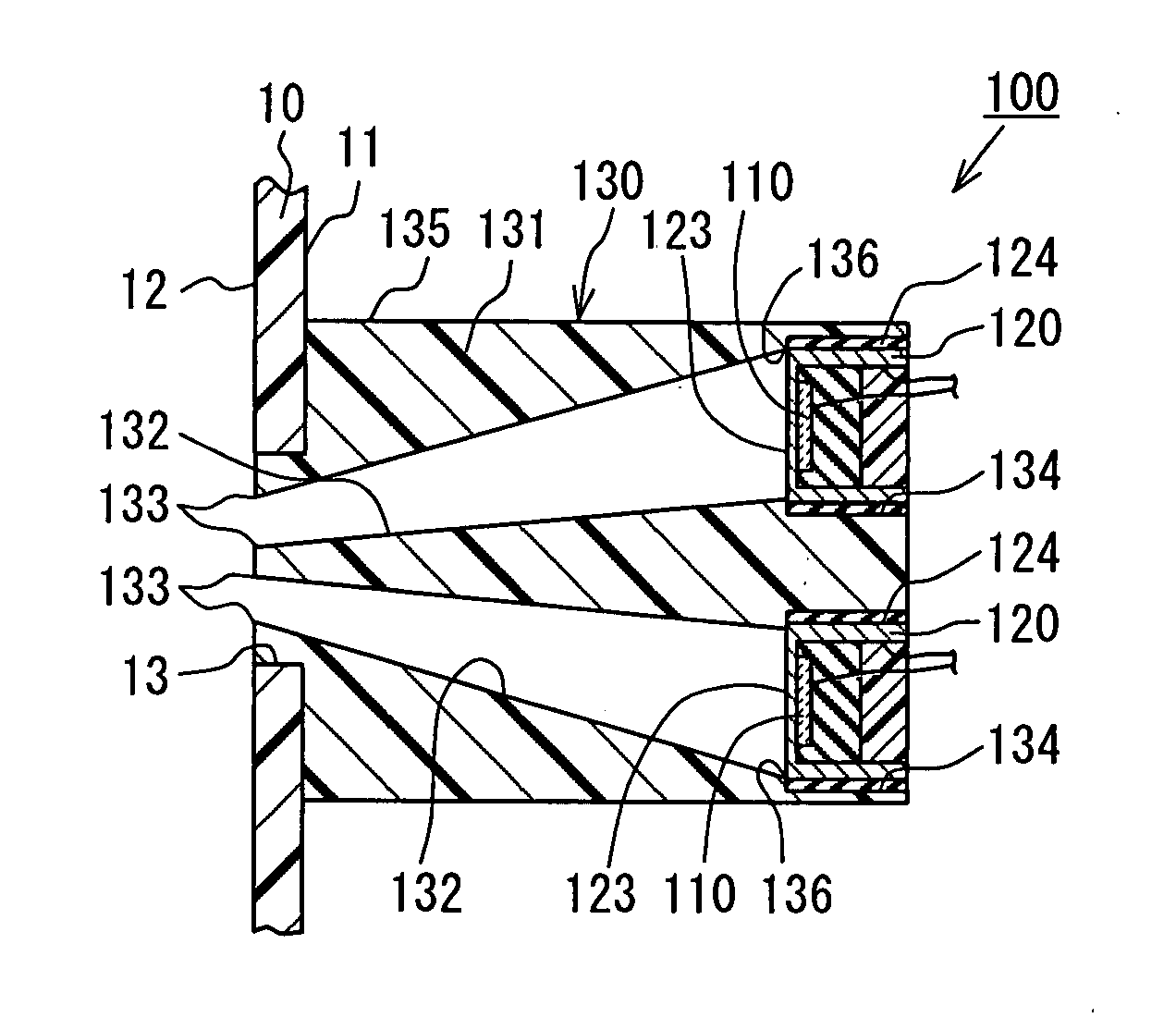
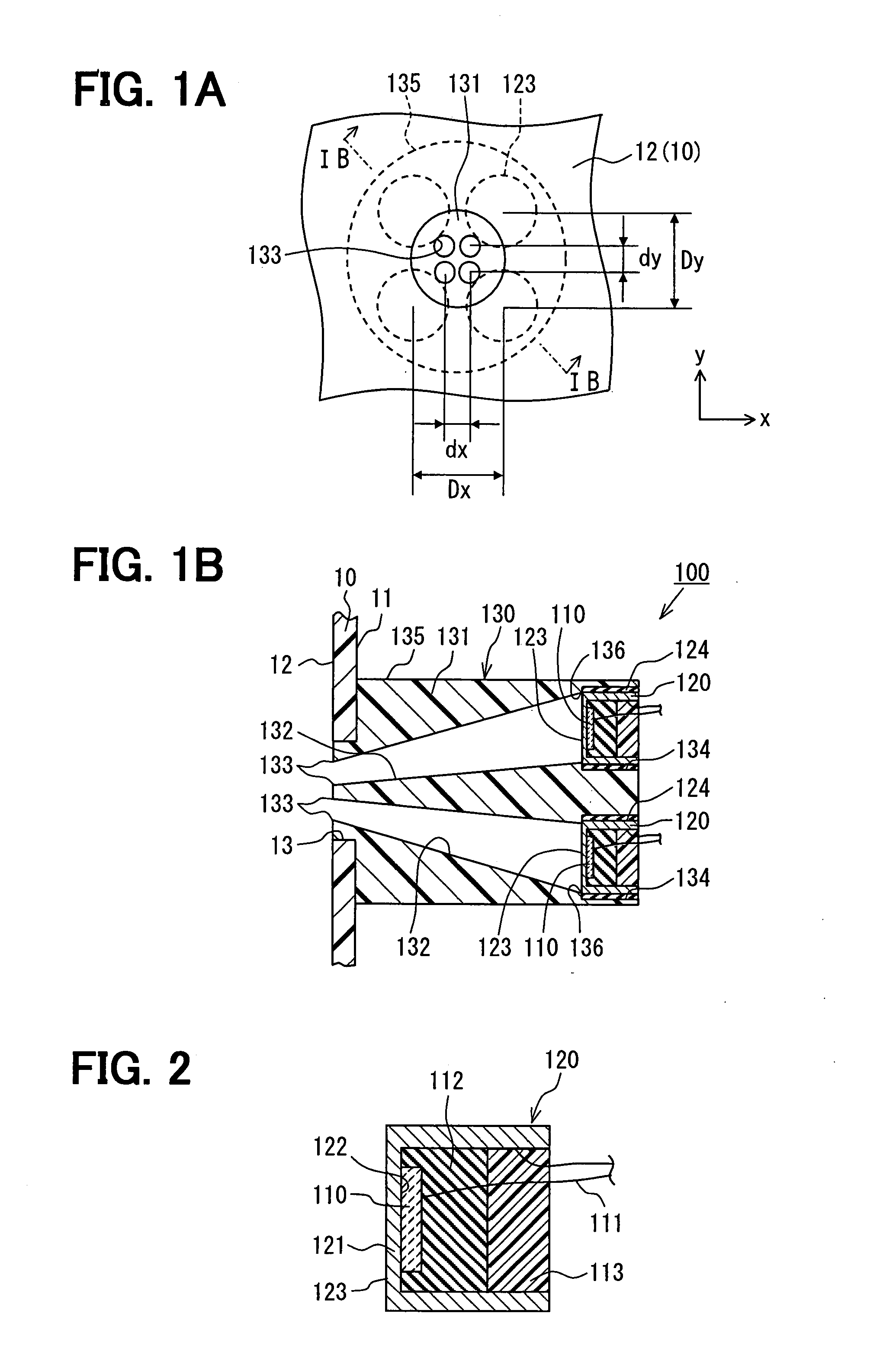
[0044]FIG. 1A and FIG. 1B are diagrams for schematically showing a structure of an ultrasonic sensor according to a first embodiment: FIG. 1A is a plan view of the ultrasonic sensor; and FIG. 1B is a sectional view of the ultrasonic sensor, taken along a line IB-IB of FIG. 1A. FIG. 2 is a sectional view for representing an enlarged peripheral portion of a housing shown in FIG. 1B. It should be understood that FIG. 1A and FIG. 1B represent such a condition that the ultrasonic sensor has been mounted on a mounting portion of a moving object, and FIG. 1A is a plan view of the ultrasonic sensor, as viewed from an exterior portion of the moving object.

[0045]In the first embodiment, a description is made of an example in which the ultrasonic sensor and an obstruction detecting apparatus containing this ultrasonic sensor are employed in a vehicle functioning as the moving object. Concretely speaking, as shown in FIG. 1A and FIG. 1B, an ultrasonic sensor 100 has been mounted on, for example...

second embodiment

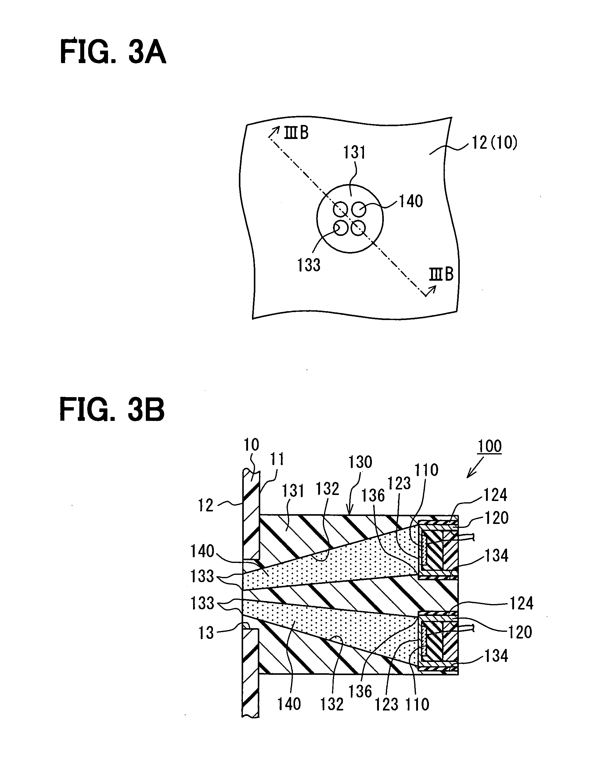
[0068]FIG. 3A and FIG. 3B are diagrams for schematically showing a structure of an ultrasonic sensor 100 according to the second embodiment: FIG. 3A is a plan view of the ultrasonic sensor 100; and FIG. 3B is a sectional view of the ultrasonic sensor 100, taken along a line IIIB-IIIB of FIG. 3A. It should be understood that FIG. 3A and FIG. 3B correspond to FIG. 1A and FIG. 1B respectively.

[0069]Since the ultrasonic sensor 100 and an obstruction detecting apparatus containing this ultrasonic sensor 100, according to the second embodiment, have many common technical ideas with respect to the ultrasonic sensor 100 and the obstruction detecting apparatus containing the ultrasonic sensor 100, which are shown in the first embodiment, a detailed description as to these common technical ideas is omitted, and different technical ideas will be mainly described in the below-mentioned specification.

[0070]In the first embodiment, the below-mentioned example has been disclosed: That is, the same...

third embodiment

[0074]FIG. 4A and FIG. 4B are diagrams for schematically showing a structure of an ultrasonic sensor 100 according to the third embodiment: FIG. 4A is a plan view of the ultrasonic sensor 100; and FIG. 4B is a sectional view of the ultrasonic sensor 100, taken along a line IVB-IVB of FIG. 4A. It should be understood that FIG. 4A and FIG. 4B correspond to FIG. 1A and FIG. 1B respectively.

[0075]Since the ultrasonic sensor 100 and an obstruction detecting apparatus containing this ultrasonic sensor 100, according to the third embodiment, have many common technical ideas with respect to the ultrasonic sensor 100 and the obstruction detecting apparatus containing the ultrasonic sensor 100, which are shown in the first embodiment, a detailed description as to these common technical ideas is omitted, and different technical ideas will be mainly described in the below-mentioned specification.

[0076]In the first embodiment, the below-mentioned example has been disclosed: That is, while the pl...


PUM


Abstract

An ultrasonic sensor includes: a first vibrator for transmitting an ultrasonic wave; multiple second vibrators for outputting a reception signal of a reflection wave; a casing having a bottom for accommodating the vibrators, an outer surface of the bottom providing a vibrating surface; and multiple tubes for guiding the ultrasonic wave. Each tube has a first opening coupled with an outside of a mobile body. An area of the first opening is smaller than an area of the vibrating surface. A distance between two adjacent first openings is smaller than a distance between two adjacent vibrating surfaces. The length of the tubes is determined to equalize a phase difference of the reflection waves at the first openings is equal to that at the vibrating surfaces.

Description

CROSS REFERENCE TO RELATED APPLICATIONS[0001]This application is based on Japanese Patent Applications No. 2006-240732 filed on Sep. 5, 2006, No. 2007-96704 filed on Apr. 2, 2007, and No. 2007-98751 filed on Apr. 4, 2007, the disclosures of which are incorporated herein by reference.FIELD OF THE INVENTION[0002]The present invention relates to an ultrasonic sensor and an obstacle detection device.BACKGROUND OF THE INVENTION[0003]Conventionally, for example, as represented in JP-A-2004-253911, ultrasonic sensors equipped with a plurality of reception-purpose piezoelectric vibrating elements are known in the technical field.[0004]The ultrasonic sensor indicated in JP-A-2004-253911 has been equipped with a plurality of piezoelectric vibrating elements and a single vibration case for storing thereinto these piezoelectric vibrating elements. These plural piezoelectric vibrating elements contain at least one transmission-purpose piezoelectric vibrating element and at least two reception-pu...

Claims


Application Information

Patent Timeline
Patent Type & Authority Applications(United States)
IPC IPC(8): G01S7/521H04R17/00G01S15/931
CPCG01S7/521G01S2015/938G10K11/22G01S15/931
Inventor KOJIMA, KIYONARIHATTORI, TOSHIHIROMATSUURA, MITSUYASUOKAMOTO, AYAKOFUJITA, MITSURU
Owner DENSO CORP
Why Eureka
Try Eureka