Network system and audio signal processor

a network system and audio signal technology, applied in the field of network system and audio signal processor, can solve the problems of band loss, inability to obtain the theoretically calculated upper limit band width, and difficulty in designing, and achieve the effect of convenient synchronization

Inactive Publication Date: 2008-09-25
YAMAHA CORP
View PDF2 Cites 13 Cited by
  • Summary
  • Abstract
  • Description
  • Claims
  • Application Information

AI Technical Summary

Benefits of technology

[0011]The invention solves the above-described problems, and it is an object to make it possible that in the case where audio signals are transported among a plurality of processors, the transported waveform data are easily synchronized each other in the sampling period domain, while easily ensuring a transport bandwidth for waveform data corresponding to a fixed number of channels in the network.

Problems solved by technology

However, such a conventional audio network system has the following problems.
Specifically, the number of lines for use in transport of audio signals is limited to the upper limit of the network band, while the number of lines capable of physically transporting changes depending on the configuration of the network, so that it is not always able to obtain the theoretically calculated upper limit band width.
For example, since the time required for data to arrive varies depending on the number of nodes from the node at the transmission source to the node at the tail and the next transmission is performed only after the data arrives all of the nodes, the more the number of nodes constituting the network exist, the more time is required for transfer of the data in the network, resulting in band losses.
Therefore, the topology for connection of equipment in the network system should be designed in consideration of how many channels the waveform data is transmitted / received from which node to which node in advance, thus causing a problem of difficulties in designing it.

Method used


Image

  • Network system and audio signal processor
  • Network system and audio signal processor
  • Network system and audio signal processor

Examples


Embodiment Construction

[0050]Hereinafter, preferred embodiments to embody the invention will be concretely described based on the drawings.

1. Outline of Audio Network System of Embodiment of the Invention

1.1 Entire Configuration

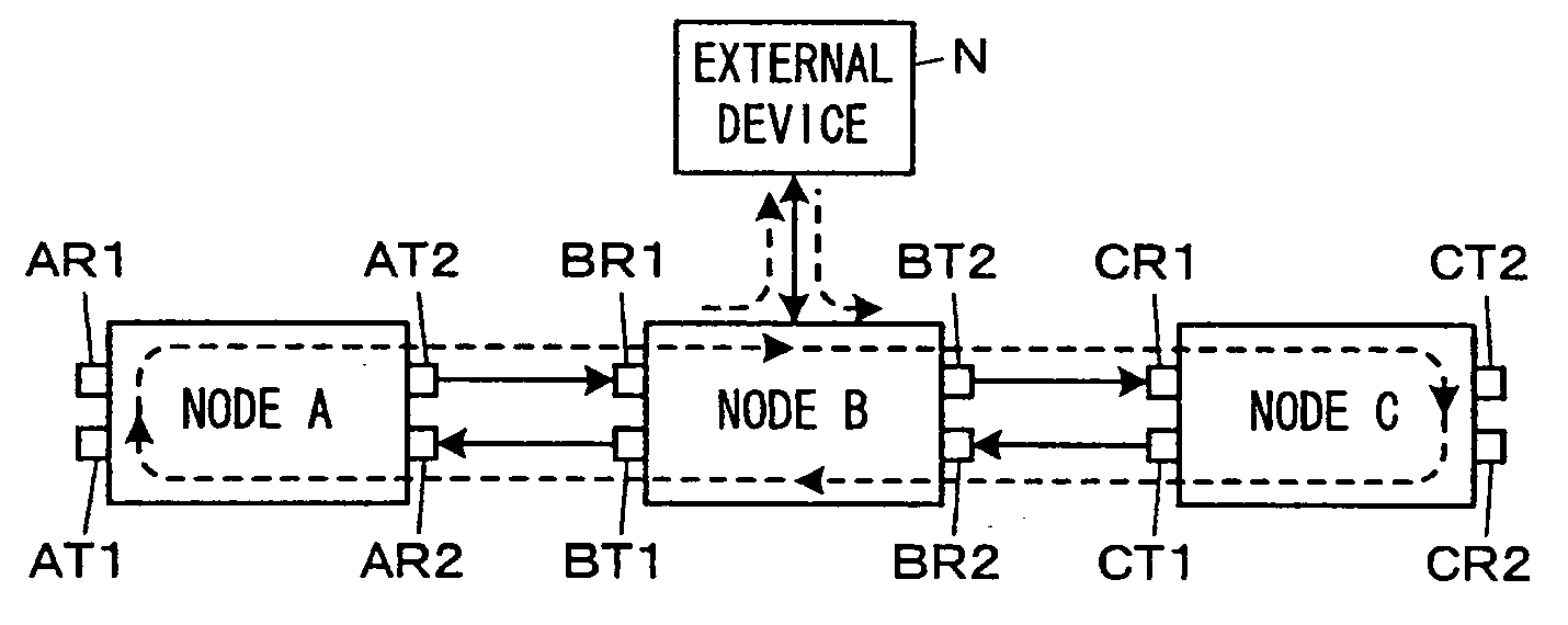
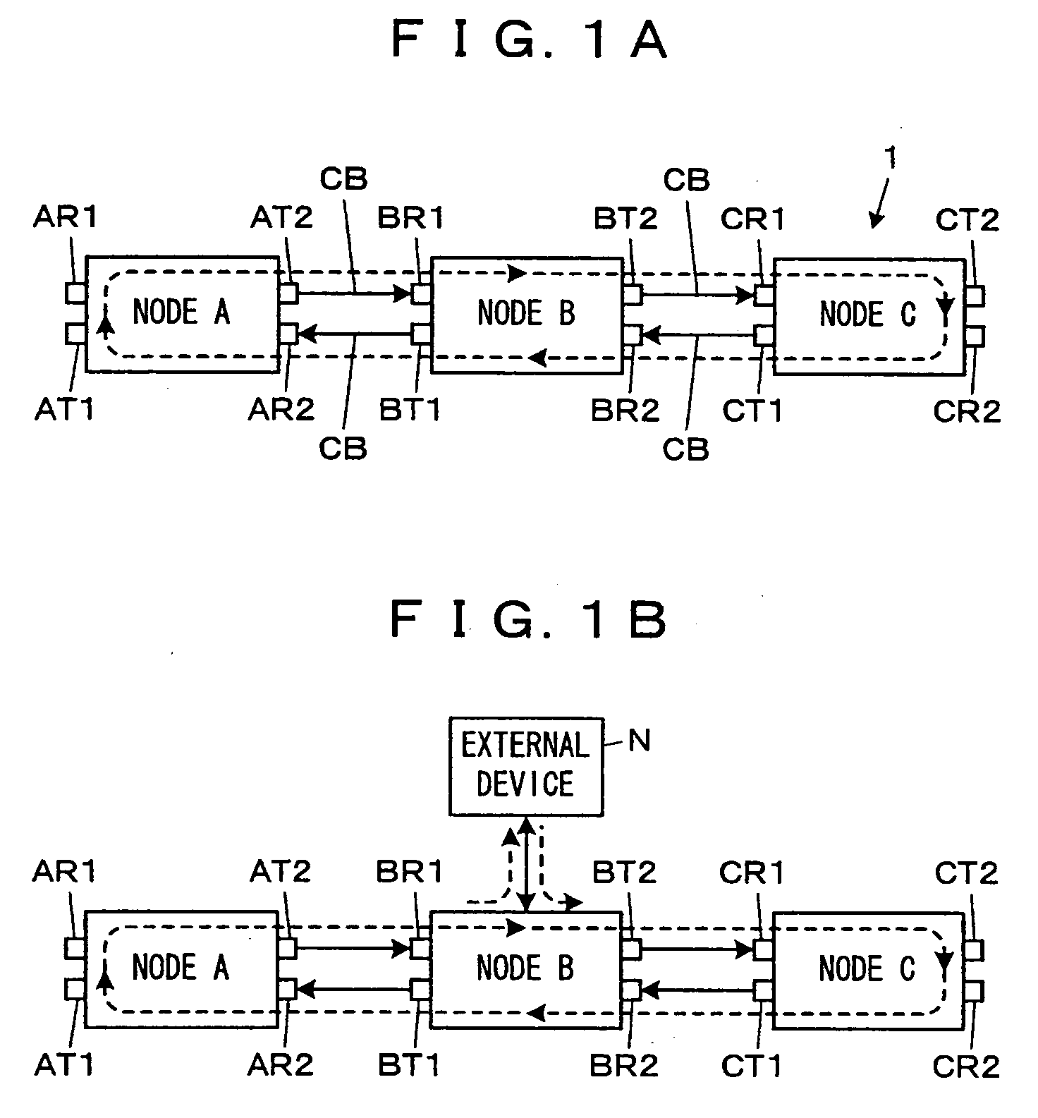
[0051]FIG. 1A and FIG. 1B show the outline of an audio network system that is an embodiment of a network system of the invention.

[0052]As shown in FIG. 1A, the audio network system 1 is constructed by connecting nodes A to C by communication cables CB in sequence, each of the nodes A to C includes two sets of reception interfaces (I / Fs) being receivers and transmission I / Fs being transmitters each of which performs communication in a singe direction. Although an example composed of three nodes is shown, any number of nodes may be employed.

[0053]In the node A, a reception I / F AR1 and a transmission I / F AT1 are one set of I / Fs, and a reception I / F AR2 and a transmission I / F AT2 are another set of I / Fs. For the nodes B and C, the same relation also applies to I / Fs with a first charact...


PUM


Abstract

An audio network system that performs transport of audio signals among nodes by cascading a plurality of nodes each including two sets of transmission I / Fs and reception I / Fs, and circulating among the nodes in each fixed period an audio transport frame generated by a master node, is configured such that the master node generates the audio transport frame in an S-th period based on the audio transport frame in an (S−k)-th period, and each of the other nodes delays the audio signals written by another node after the audio transport frame is generated by the master node until the audio transport frame is transmitted to the self node, by k period(s) with respect to the other audio signals, for use in signal processing.

Description

BACKGROUND OF THE INVENTION[0001]1. Field of the Invention[0002]The present invention relates to a network system for transporting audio signals between a plurality of nodes, and an audio signal processor constituting such a network system.[0003]2. Description of the Related Art[0004]Conventionally, an audio network system has been known for transporting audio signals between a plurality of nodes, and is used in concerts, dramas, music production, private broadcasting, and so on. Known examples of such an audio network system include CobraNet (trademark), SuperMAC (trademark), and EtherSound (trademark) as described in the following references 1 to 3.Reference 1: “CobraNet™”, [online], Balcom Co. [Retrieved on Mar. 21, 2006] Internet <URL: http: / / www.balcom.co.jp / cobranet.htm>Reference 2: “SuperMAC™-Sony Pro Audio Lab, Oxford”, [online], Sony Pro Audio Lab, [Retrieved on Mar. 21, 2006] Internet <URL: http: / / www.sonyoxford.co.uk / pub / supermac / >Reference 3: Carl Conrad, “Et...

Claims


Application Information

Patent Timeline
Patent Type & Authority Applications(United States)
IPC IPC(8): H04L12/56H04L12/42H04L12/423
CPCH04J3/062H04J3/085H04J3/0691H04L12/42H04L12/437H04L12/40169
Inventor NAKAYAMA, KEI
Owner YAMAHA CORP
Why Eureka
Try Eureka